

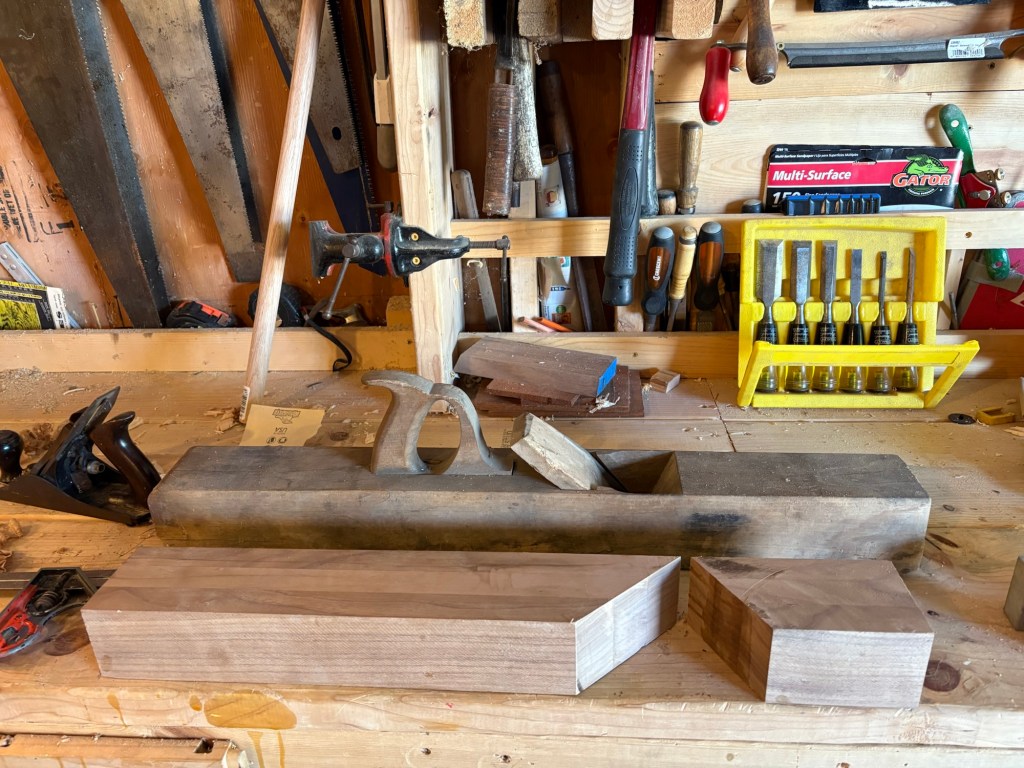
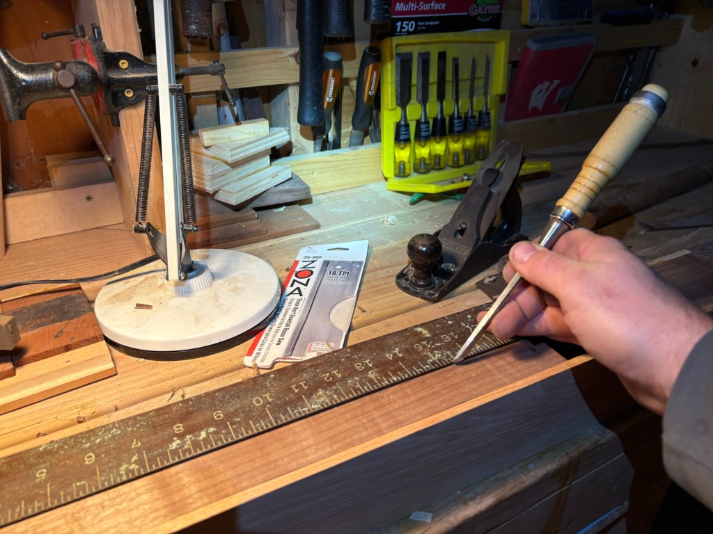
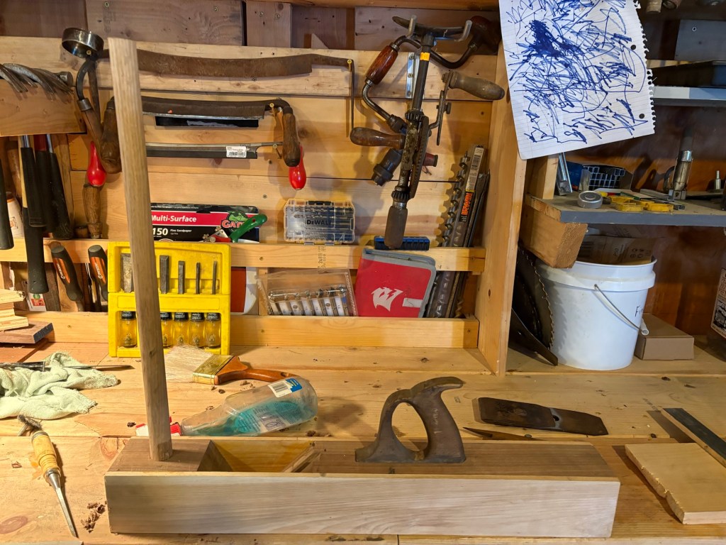
Almost a year ago, Daddy and Winnie went to an estate sale where they were selling a bunch of old tools. Most of the good ones had been sold already, but we were able to pick up a few vises and an old wooden tri-plane.
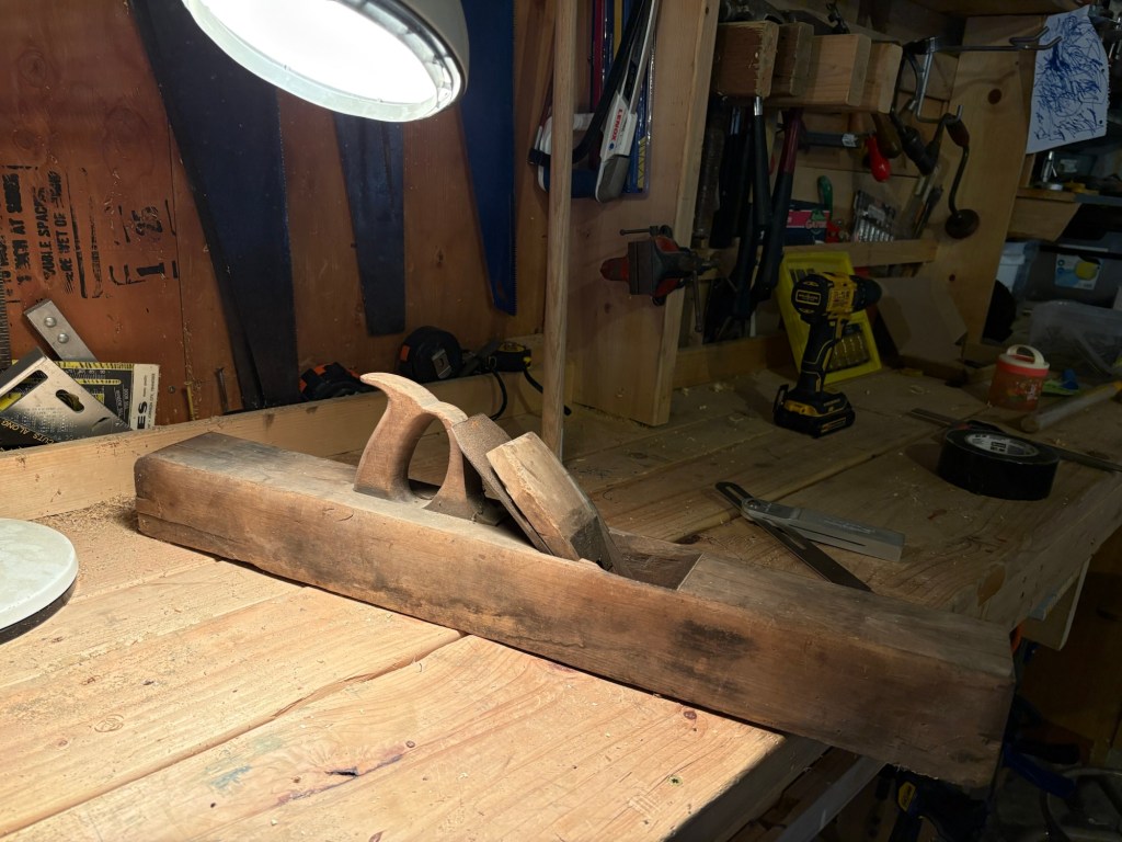
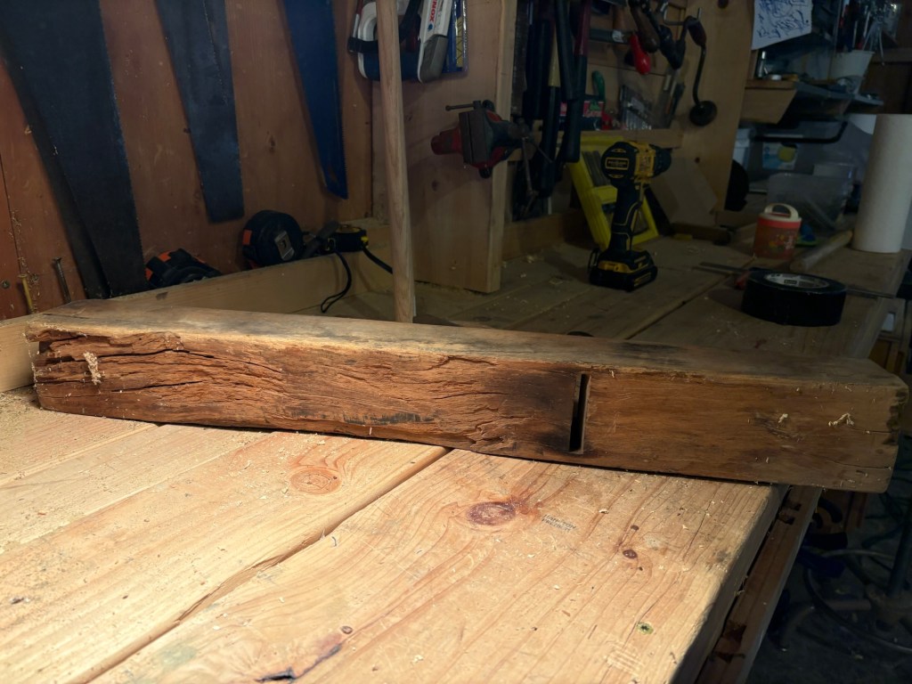
It was quite cheap (of course I don’t remember the price) because the wood was completely dry rotted out.
The double iron was still salvageable, so I bought it with the intention of rebuilding it one of these days.
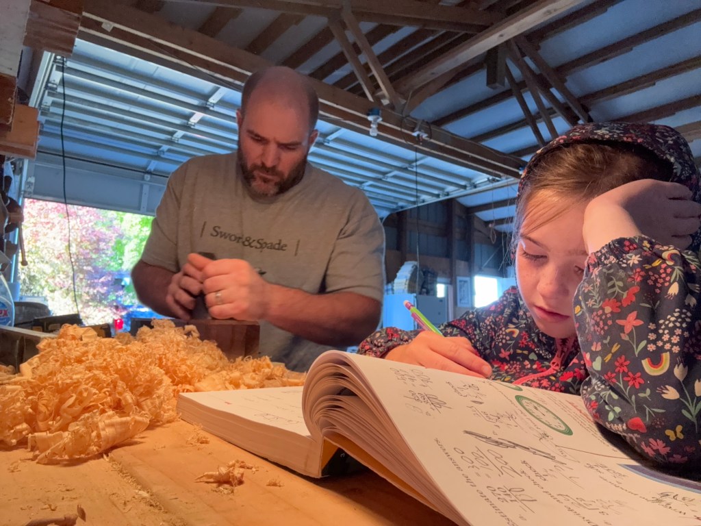
Well, one of these days arrived. Actually, several of these days as it turned out, signaled by the return of the school year, and the realization that with Evie and Ellie moving in to higher grades, I can’t leave them to do their school and go off to work in the garden, and only check back in on them a couple times an hour. I have to be there for the whole morning. So now I need projects that I can do while directing and correcting home school, hence the increase in woodworking projects.
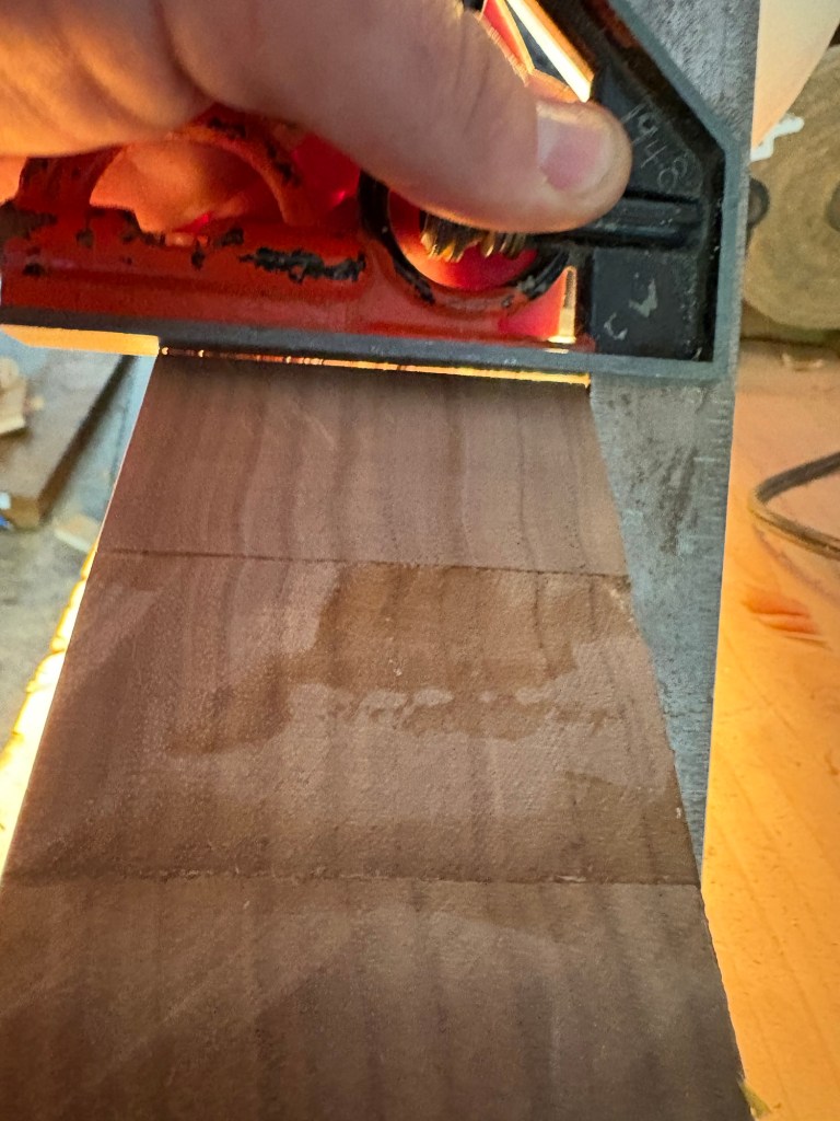
The other piece that came up was a literal piece of wood. A local second use building store advertised an 8 foot plank of 5″ quarter sawn hickory (they didn’t know it was quarter sawn, or didn’t mention it on the ad at least). Quarter sawn is useful for hand tools like planes that need to stay true, because there is no pith wood, so theoretically it should expand and contract evenly with the seasons.
My original thought was simply to chop the plane out of a section of old 4×4, but after doing a bunch more research on hand planes, I decided to go with laminating one out of hardwood instead.
Hence the quarter sawn walnut. This would form the body of the plane, after I had cut and laminated it.
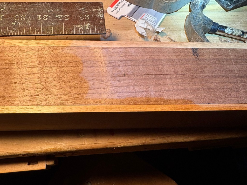
After glue up the two halves looked like this.
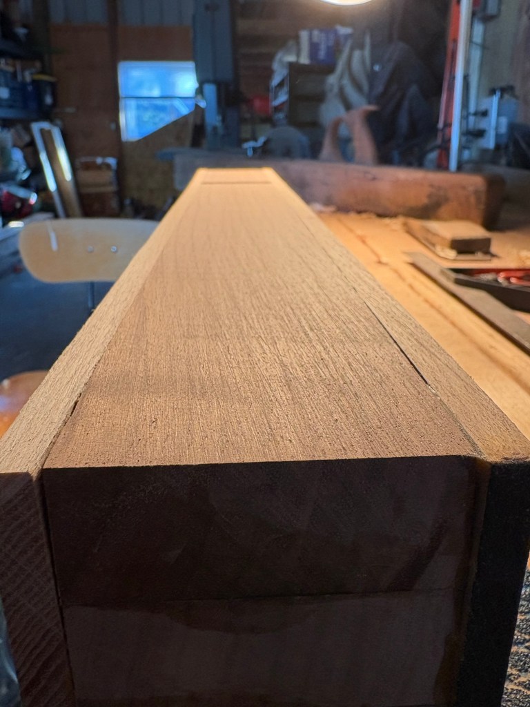
At first there was a slight cup in the middle of the sole, but I planed that out.
Yes, I had to use a plane to make a plane.
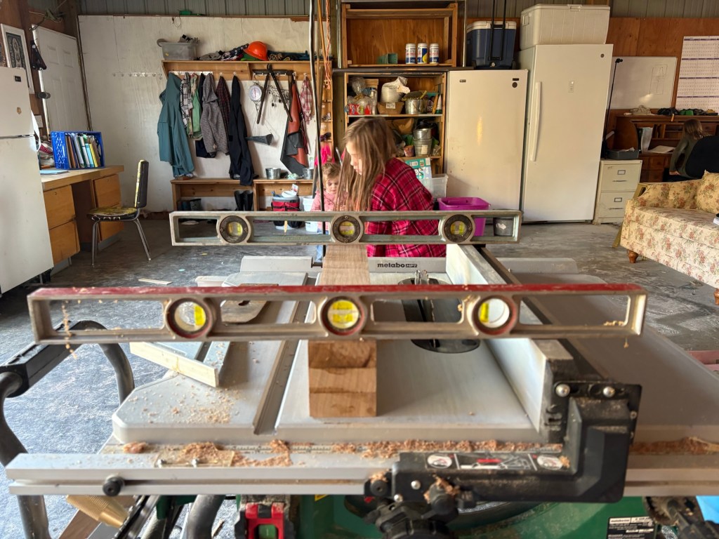
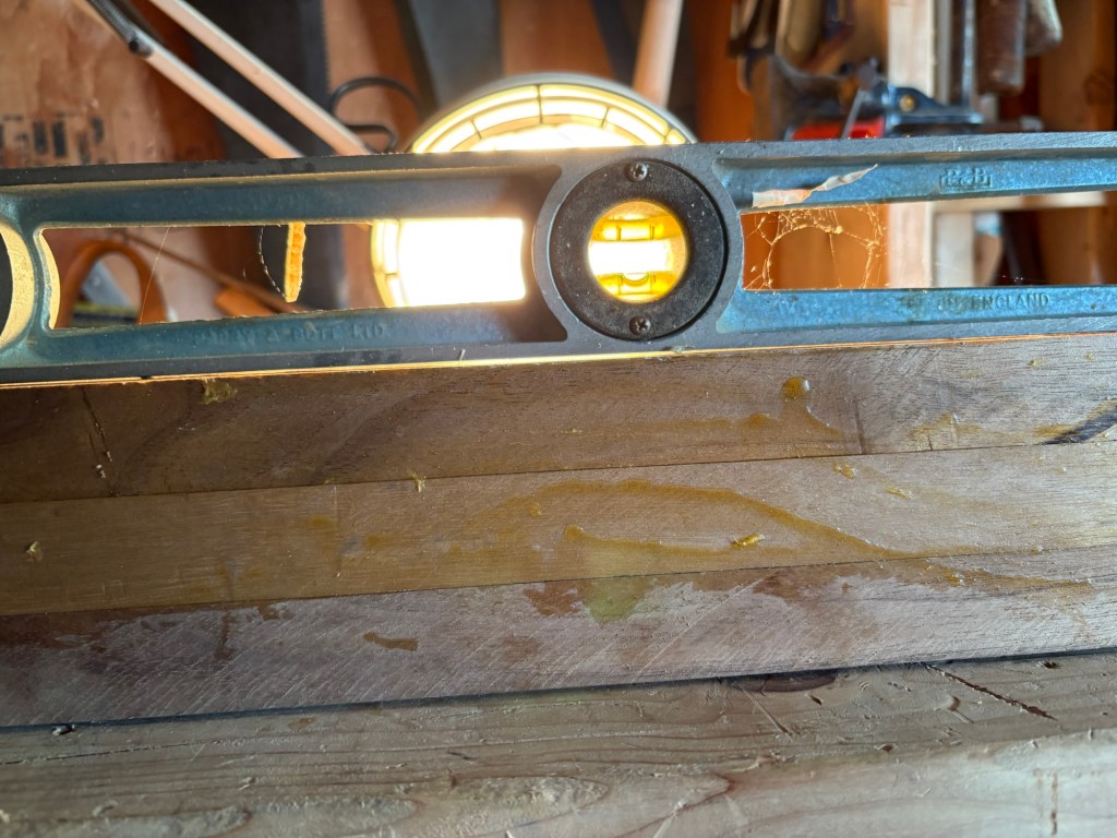
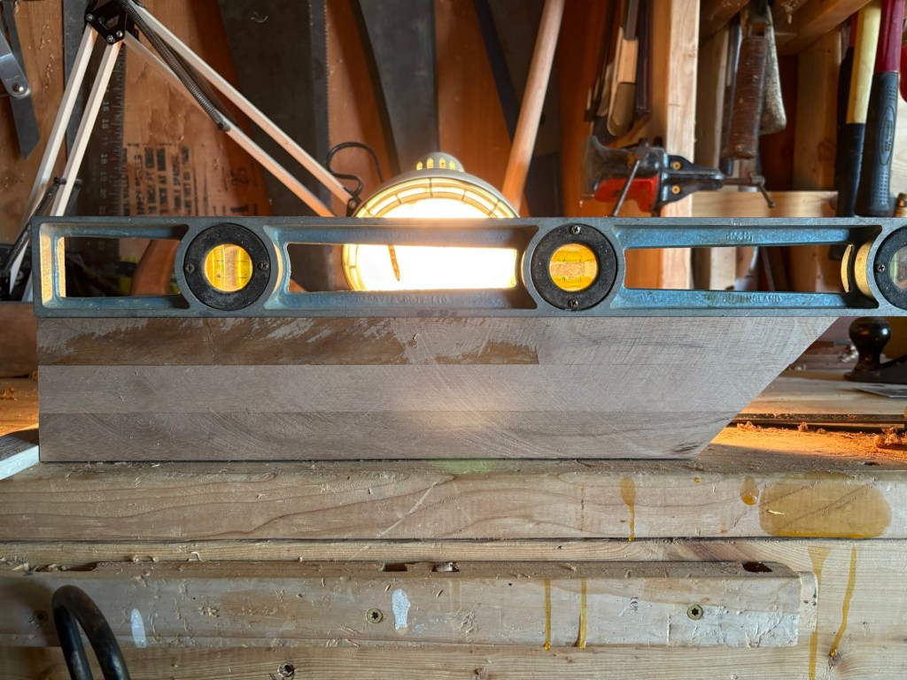
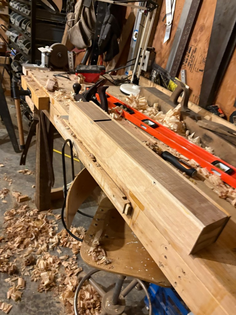
I also used a pair of levels as winding sticks…
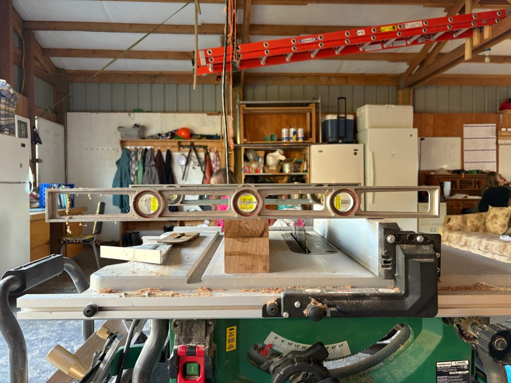
to make sure…
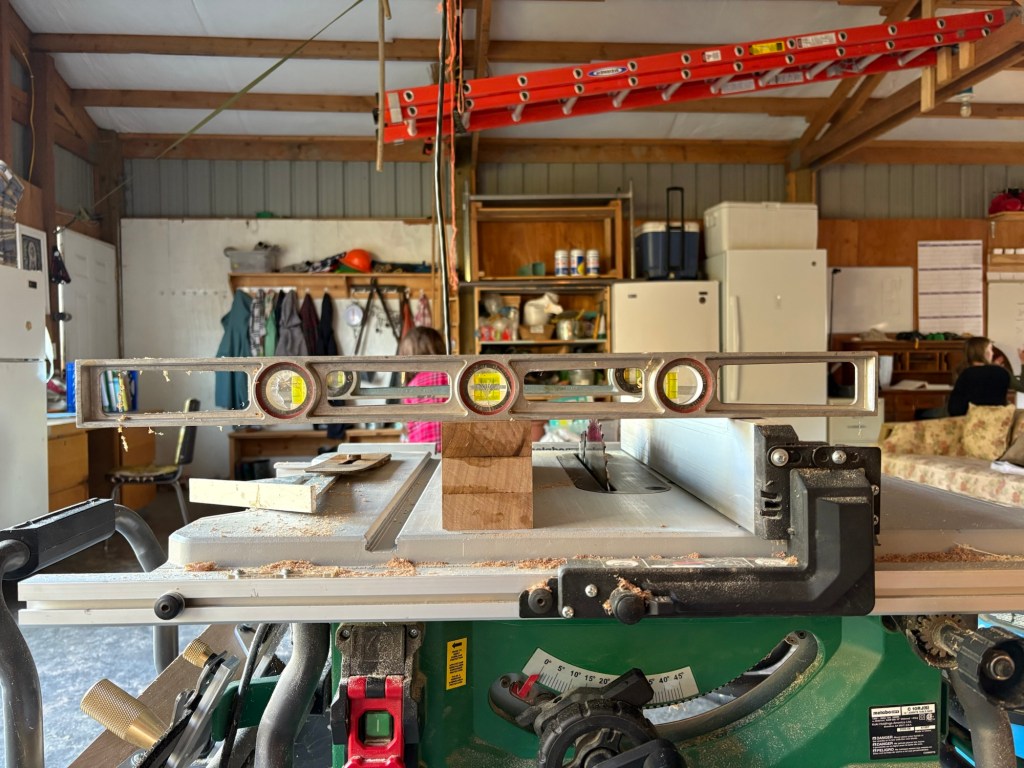
The sole was dead flat without the slightest twist.
Honestly, looking back, I am wondering if I could have postponed all of that sole work until the final glue up, and focused that time and effort on the sides and most especially on the bed. The question is whether I could have gotten the sides and bed squared and true without having the sole already flattened to use as a reference face.
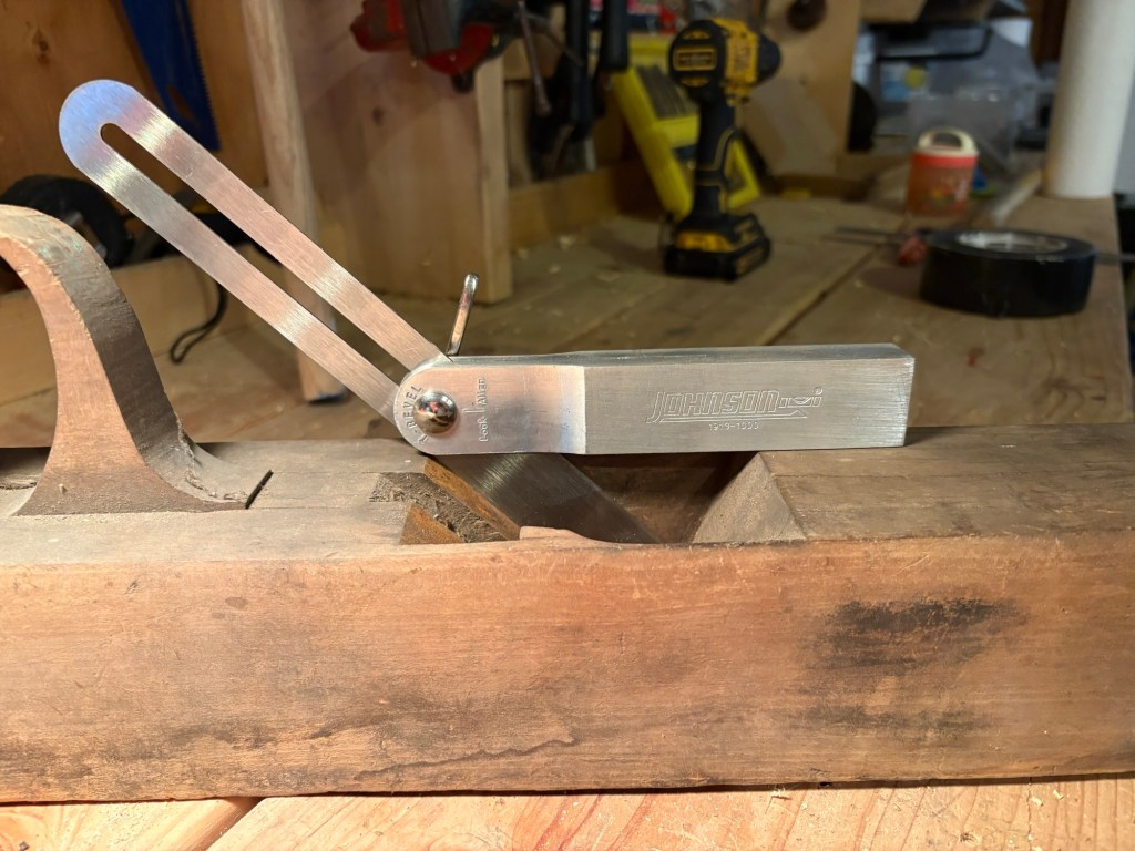
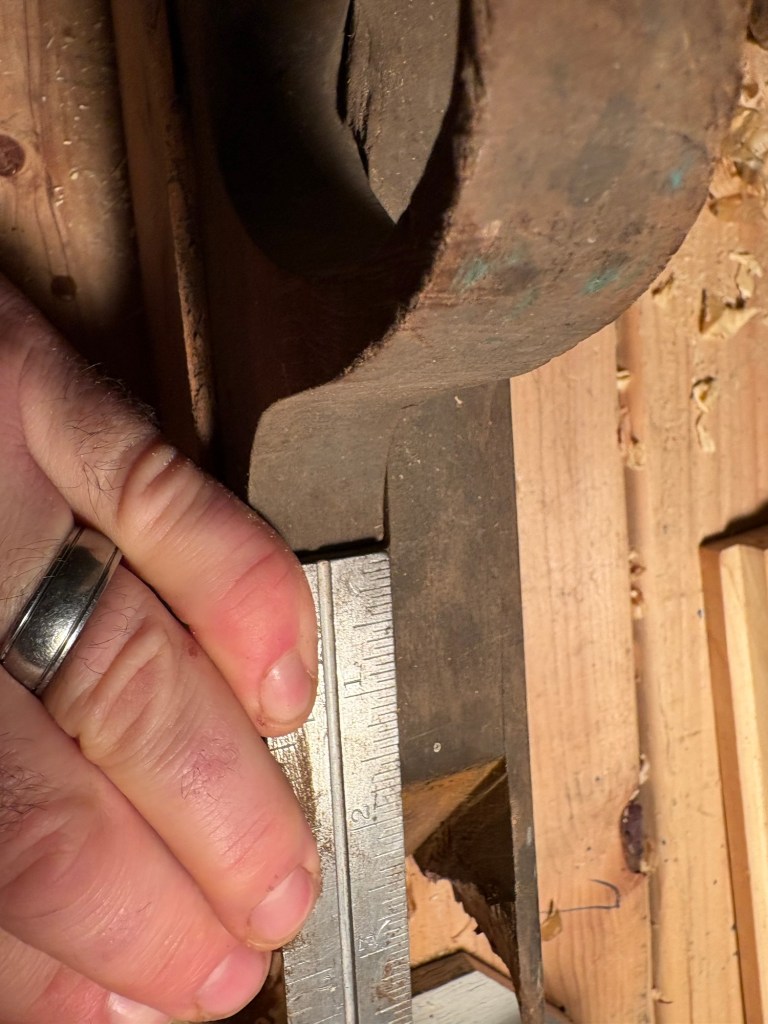
This is a close up of the slanting bed (what would be the frog in a modern metal hand plane). This is what the steel of the plane actually rests on, and this is the most critical piece at this juncture. It MUST be absolutely dead flat, and the top and bottom edges MUST be absolutely dead square to the sides of the sole. You can see in the picture above that the top edge is not exactly square, so I planed a little off the left hand side and brought it into true with the sides.
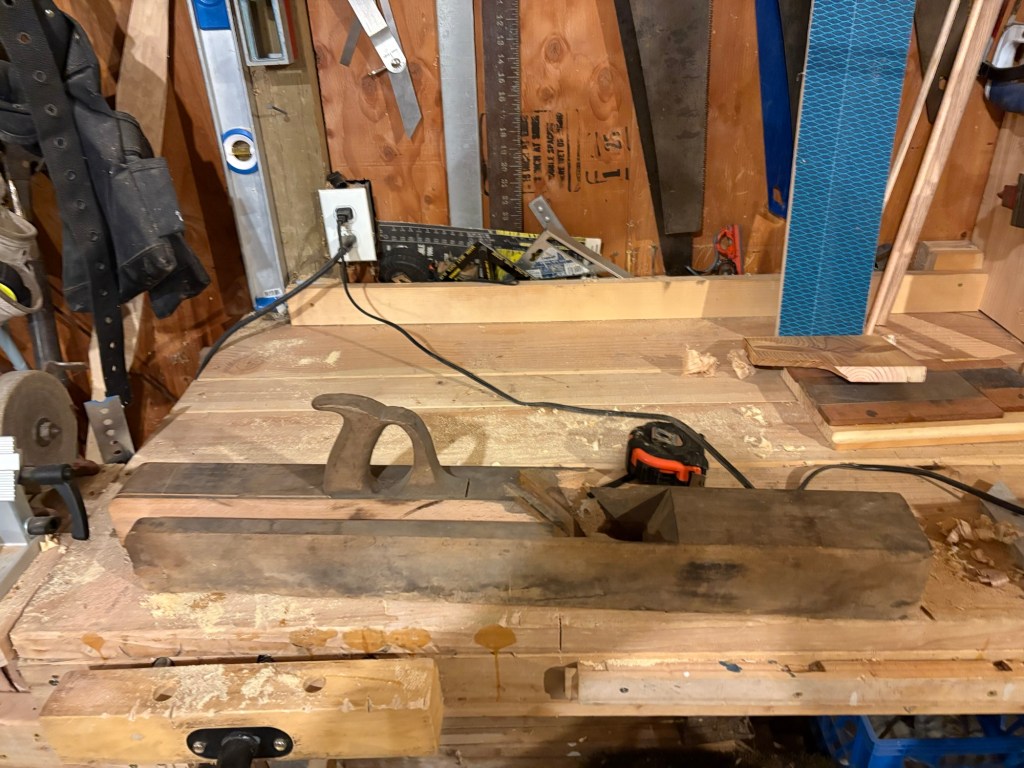
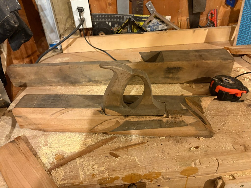
Now ready for the cheeks and glue-up.
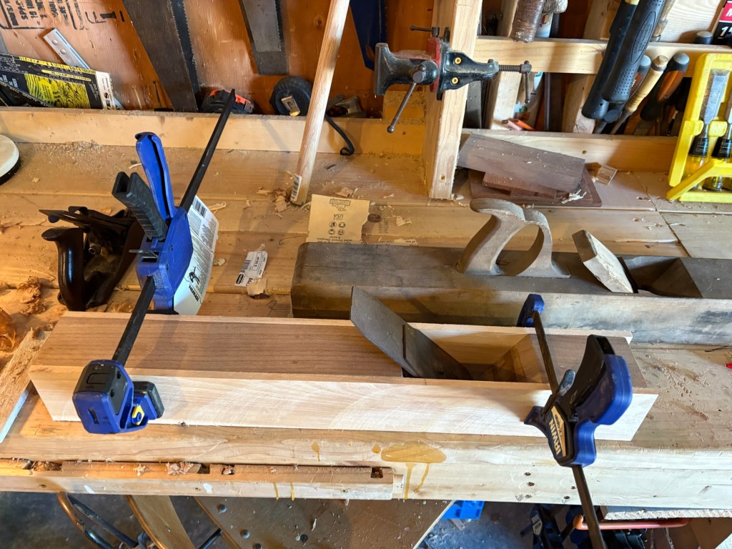
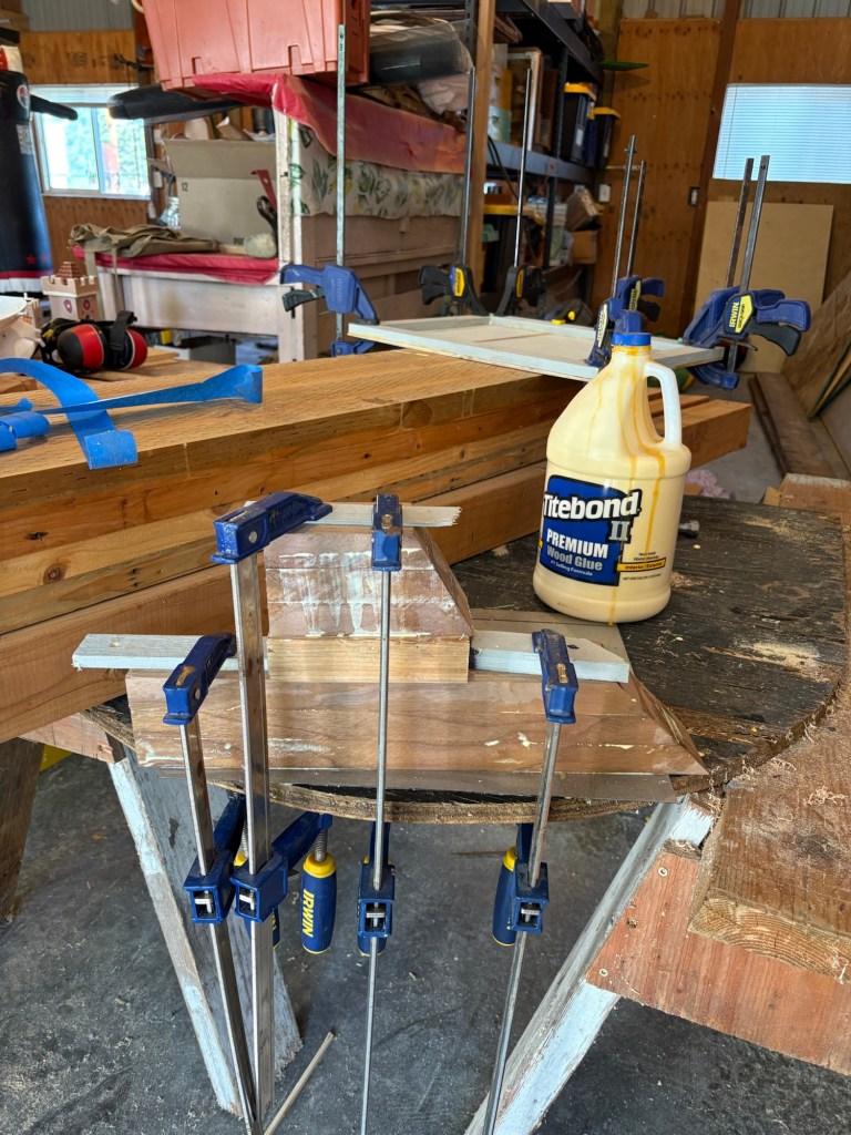
The cheeks are made of a hickory plank that I ripped down to 3/8 inch. Lesson learned, This is a thoroughly inadequate number of clamps. There are other ways I could have built various jigs to apply more pressure, and, more importantly, more equal pressure. Alas, I was running out of daylight, and was in a hurry. Fortunately, I had spent a good deal of time planing the components flat so it didn’t come out horribly.
It came together.
Not perfectly, though. There was a little gap on the tail end.
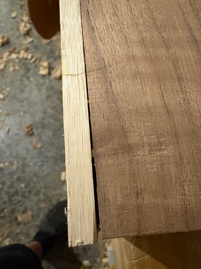
Hopefully the gap does not spread over the seasons as the wood shrinks and expands.

I try never to be in a hurry in the workshop because it is not just a workshop. It is also a school room, a gym, a play area and a nap area. And some days, you just don’t get anything done, or at least, not what you had planned.
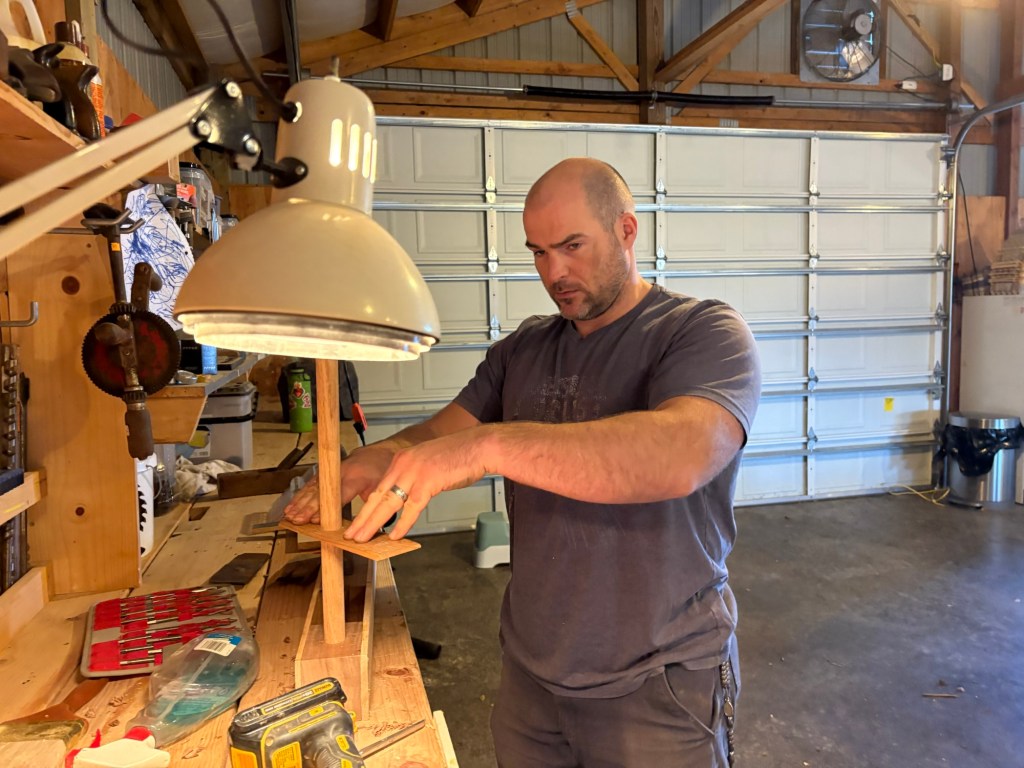
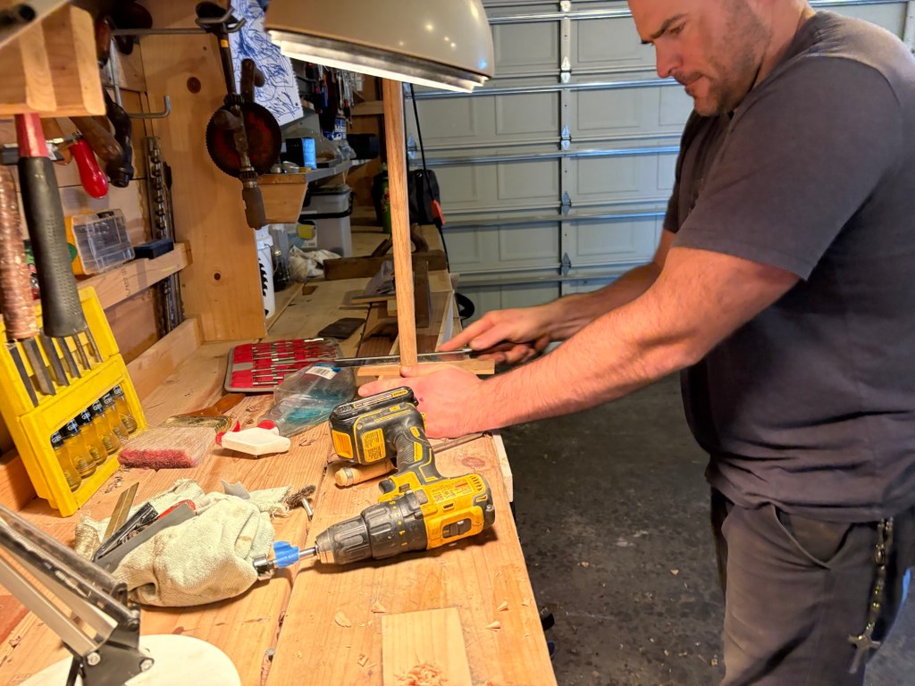
Then several days where all the shop time is spent slowly planing first the sole flat, then both sides square and flat off the sole. This will probably be used mostly as a shooting plane, so it is absolutely essential that the sides be perfectly square to the sole.
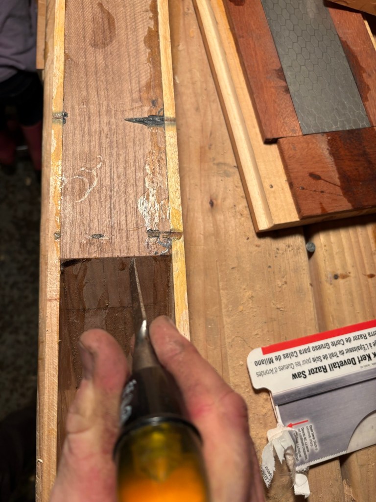
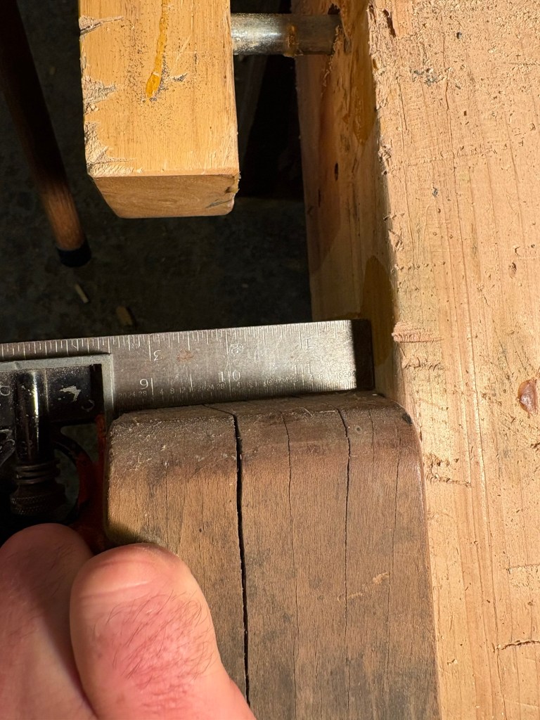
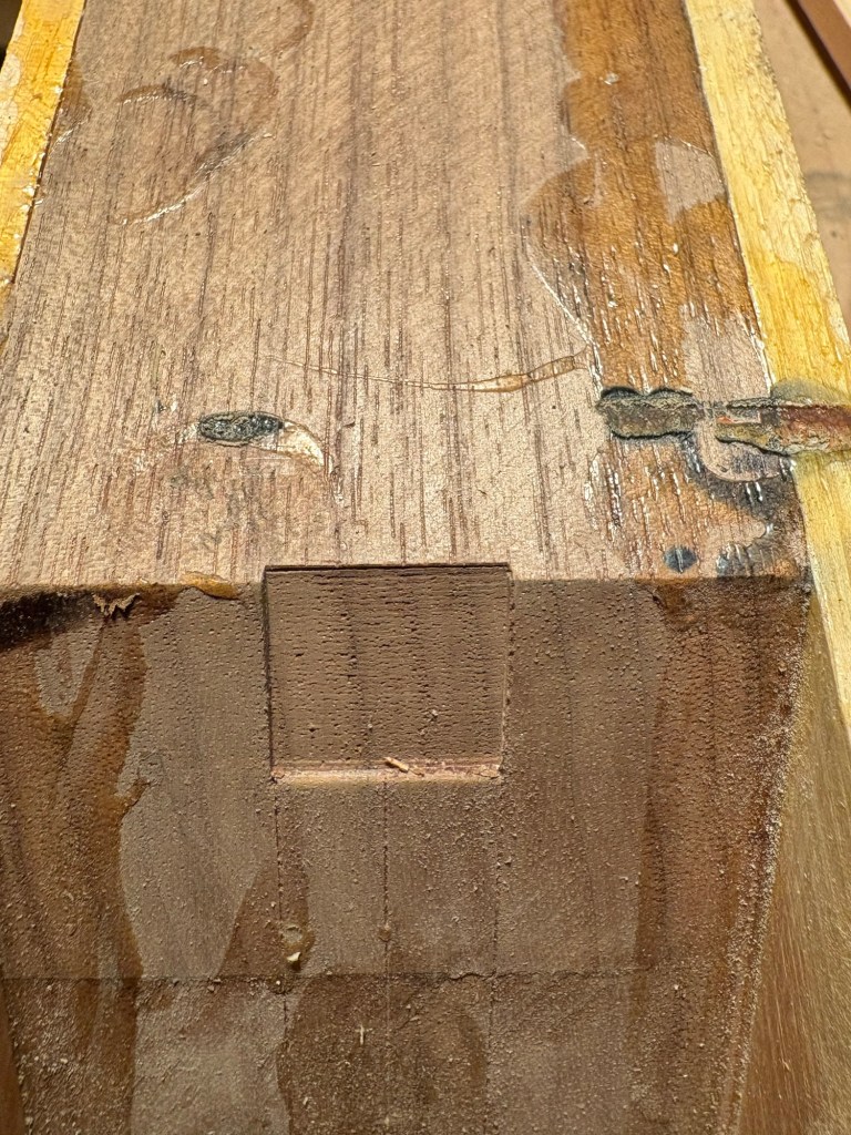
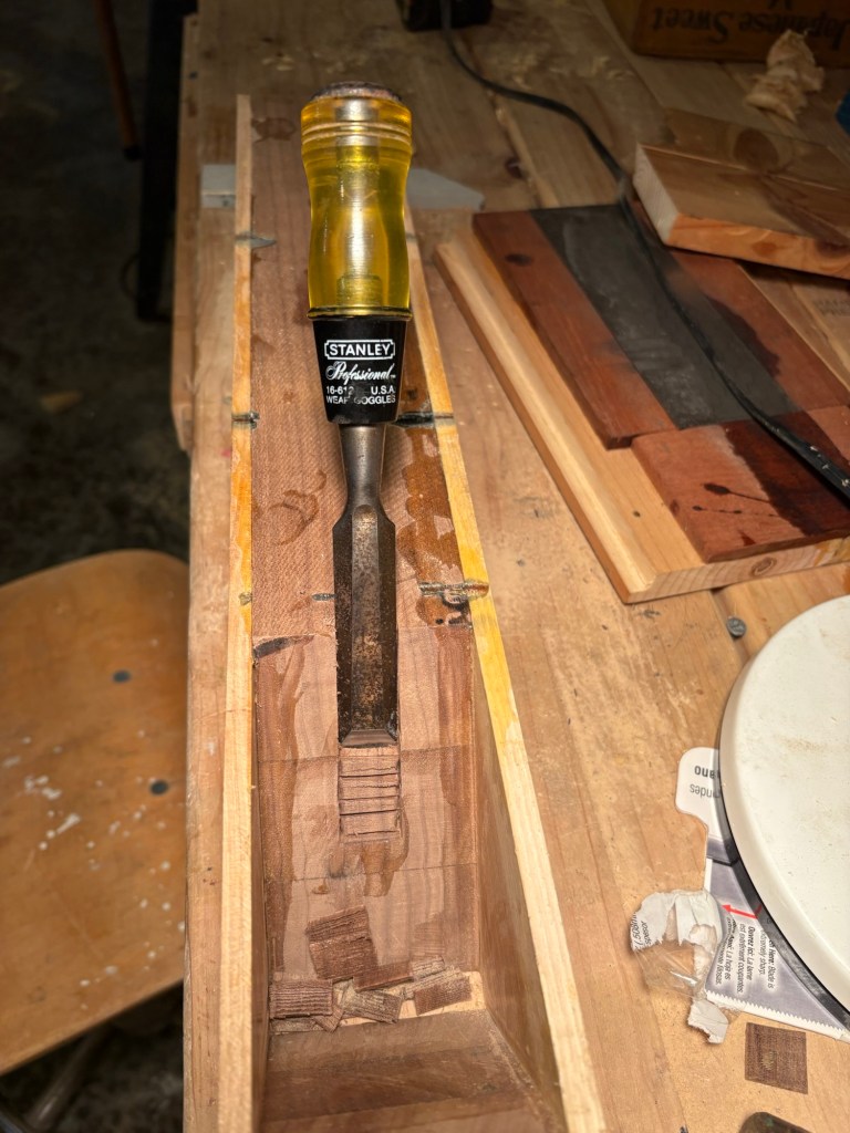
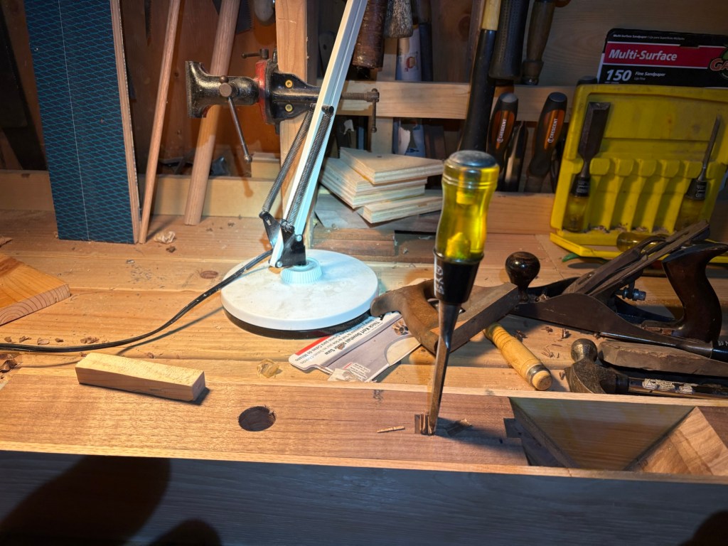
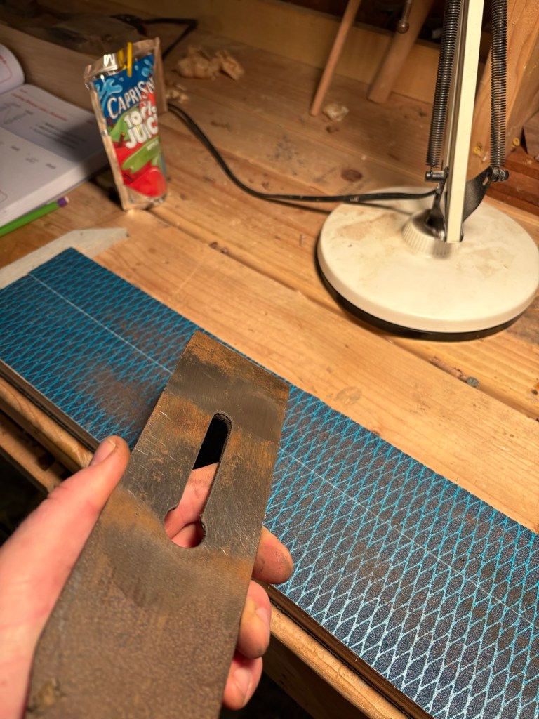
The next step was to mark out the slot to receive the screw on the under side of the blade. This is centered off the hickory body, not off the cheeks, because they are not exactly uniform thickness.
The groove is exactly 3/4 wide, or the width of my (really uncle Adam’s) 3/4 inch chisel.
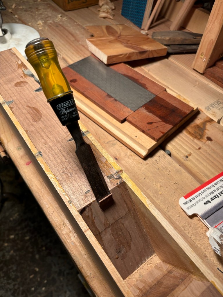
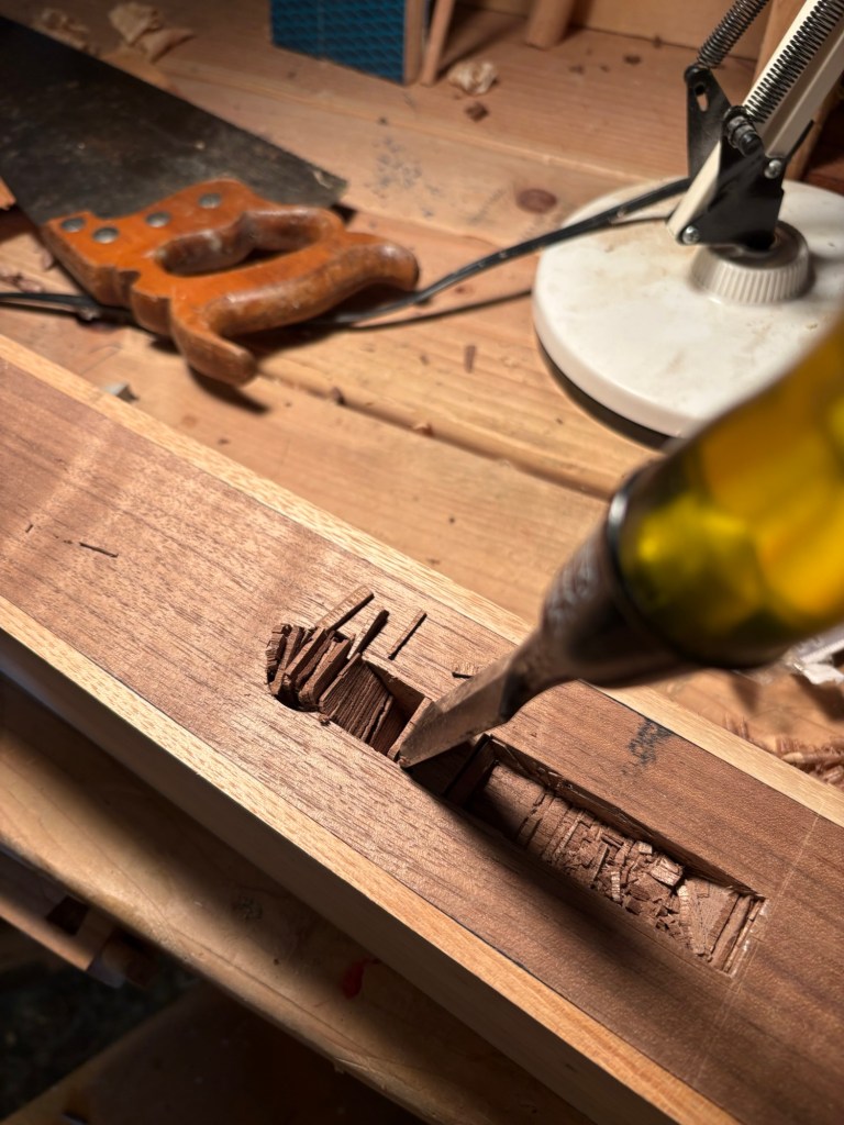
I have been working a good deal on my sharpening skills over the last few months. This is not a bad chop out, for my first attempt. I like how the walnut handles under the chisel.
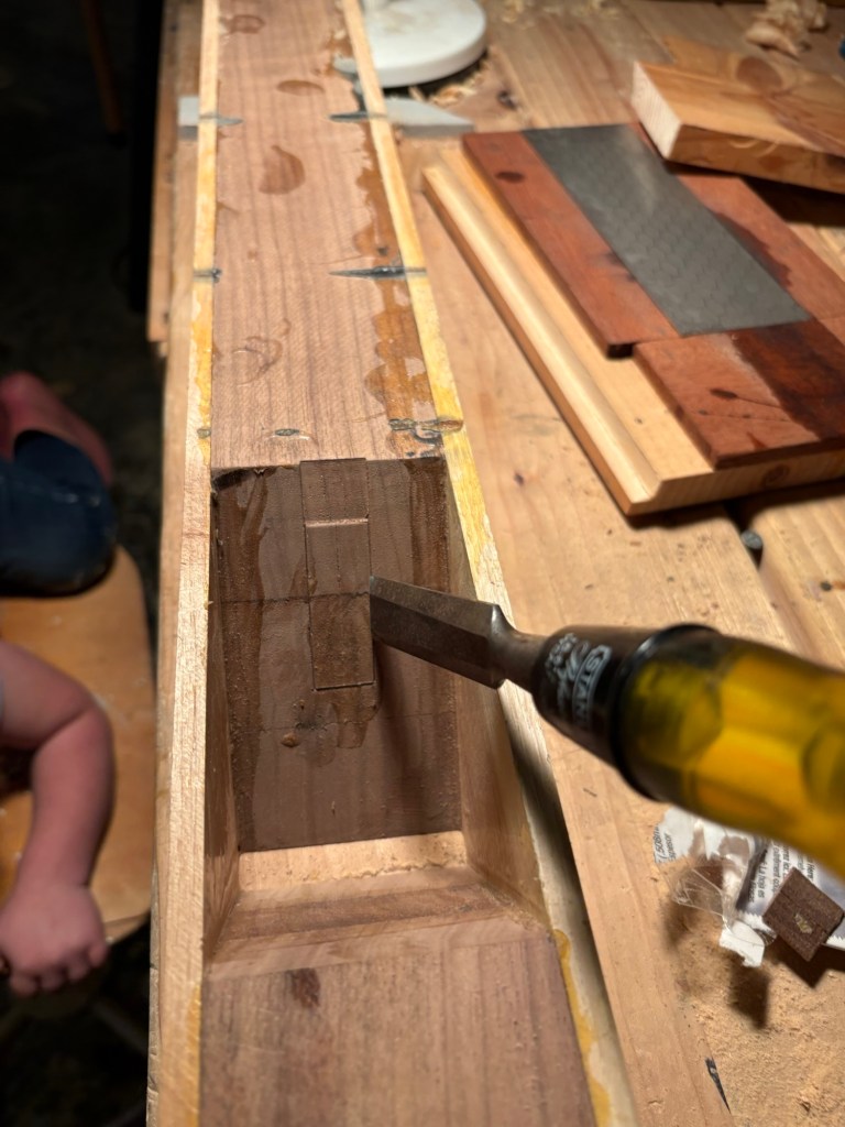
Then tapping out the outlines. I later learned that this was not the optimal approach and can result in a mortice wider than intended if it pushes the line back. However, because this is just a groove for a screw head to slide down into, the exact dimensions are not critical.
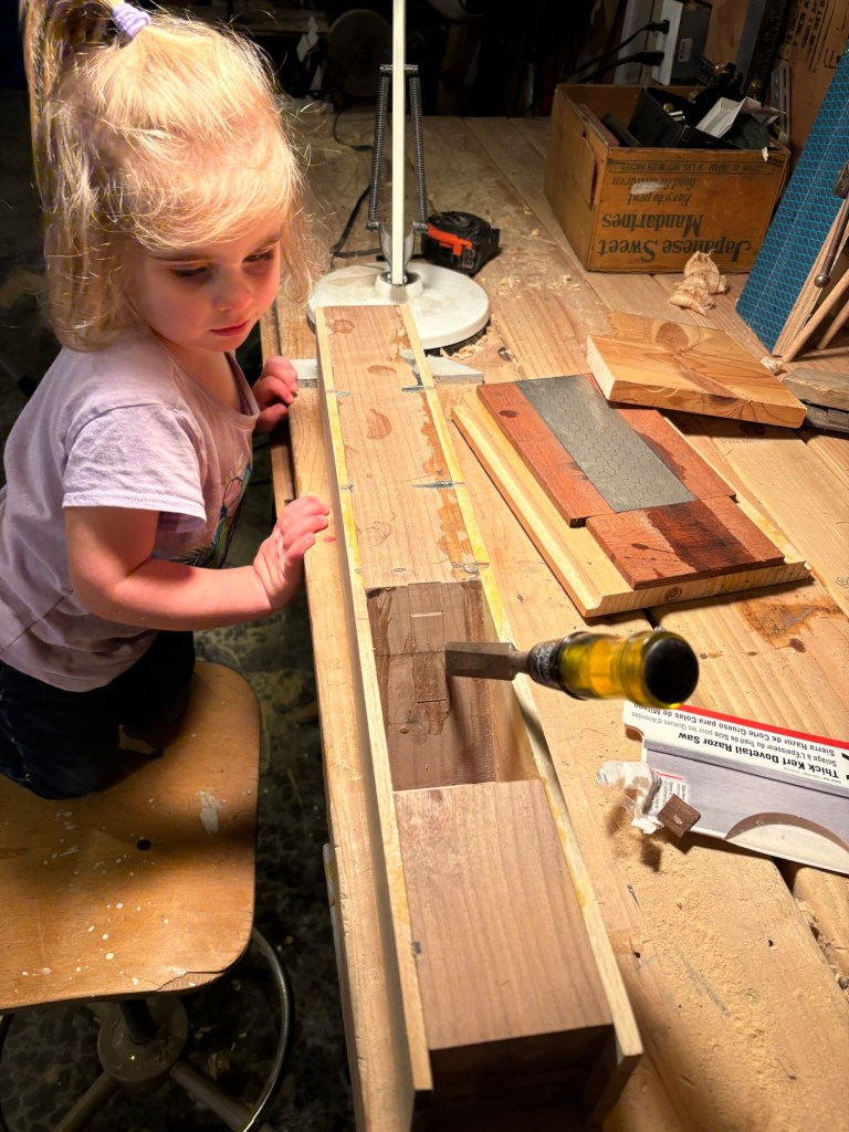
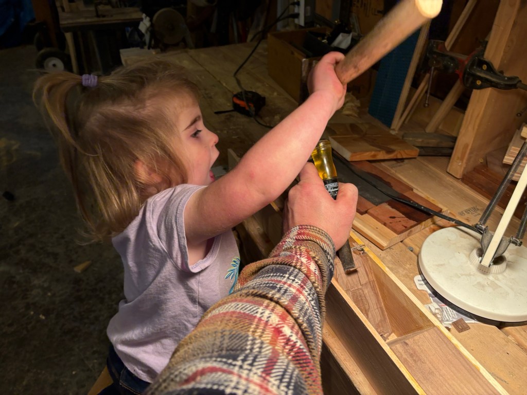
“Daddy, what are you building? Can I help?”
Of course you can!
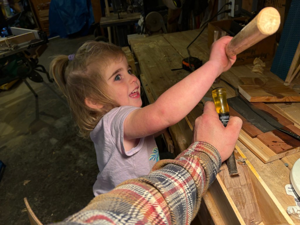
Yes, it’s a metal hammer, but it is also a metal capped chisel. Not classy, but sufficient for this stage in my learning.

Tap in the ladder steps.
Then carve them out.
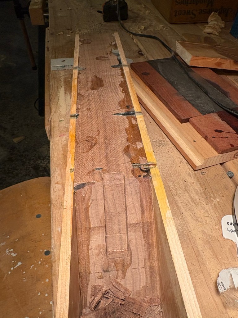
And there it is. A nice serviceable groove for the screw on the back of the blade.
With this in place, the next step was to attach the tote (handle). Of course I could have made a handle from scratch, but…
Why bother when the original plane had a perfectly good and very comfortable handle. A touch small for my hand, but then most handles are.
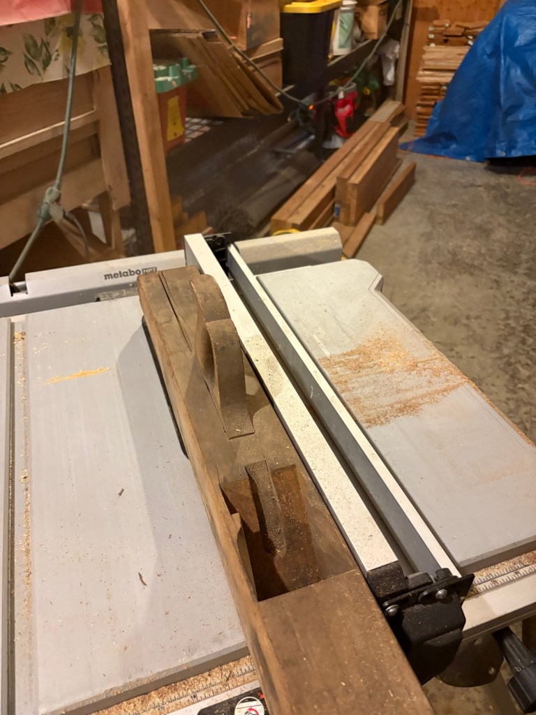
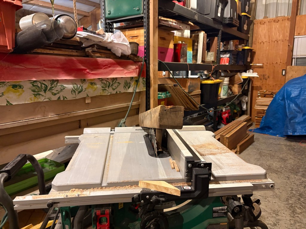
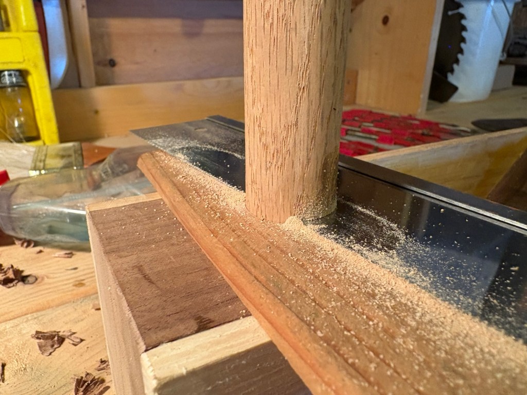
It was the work of a moment to set up the table saw and rip down the length of the plane.
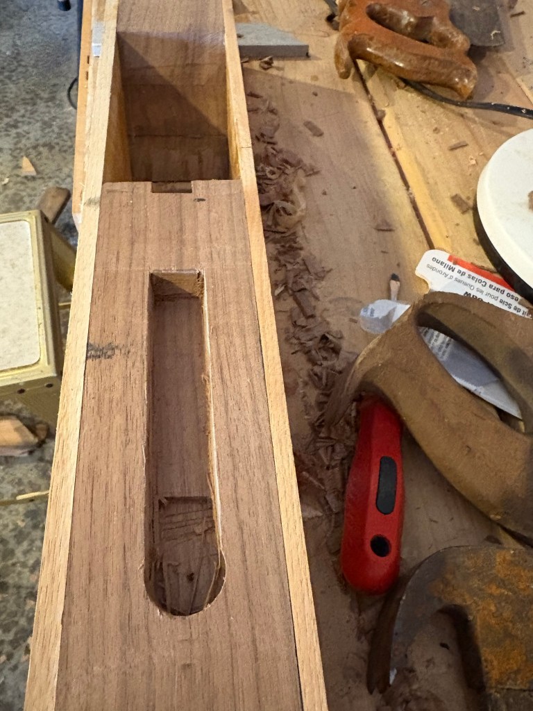
And pop the tote out of its mortice.
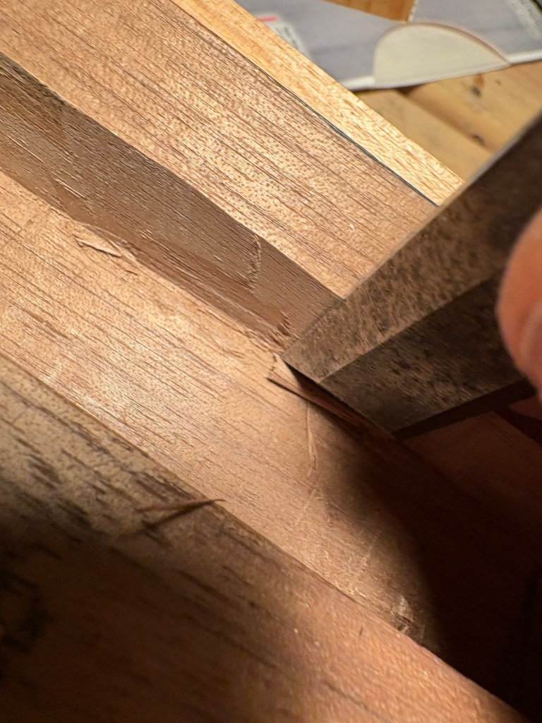
That was easy part. The more difficult part is cutting a new mortice in the new plane to receive the tote. Unlike the groove for the screw head, this has to be perfectly fitted.
First measuring off the old plane to get an idea of where to set the end of the mortice.
But also, trying it in place with my own hand to see if I like the placement. As it turns out, I liked it set back just a little so that my index finger just touches the steel.
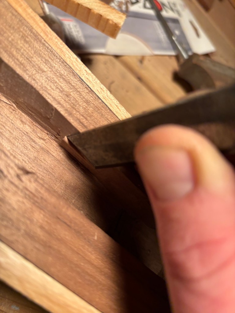
Then selecting the chisel. The 3/4 inch was too narrow.
The one inch was just a bit too wide.
But my 1″ Forstener bit fit nicely in the round end of the existing mortice on the old plane.
So when laying out my marking lines (using a chisel because I was in workout shorts and didn’t have my knife)…
I marked the center of the bit…
And scratched the round end of the mortice with the bit itself. After verifying fit,
I drilled out the round end of the mortice.
And chopped out the straight portion with the chisel.
This time, armed with more youtube videos, I stayed away from my lines as long as I could.
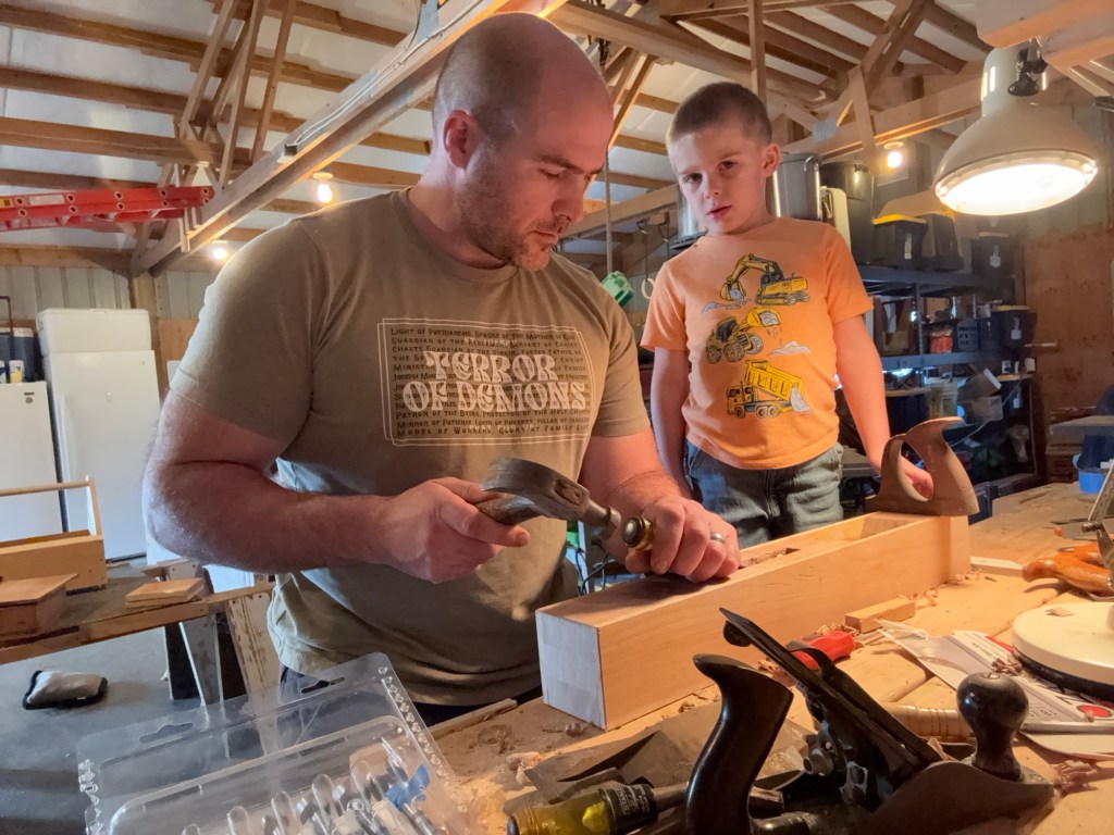
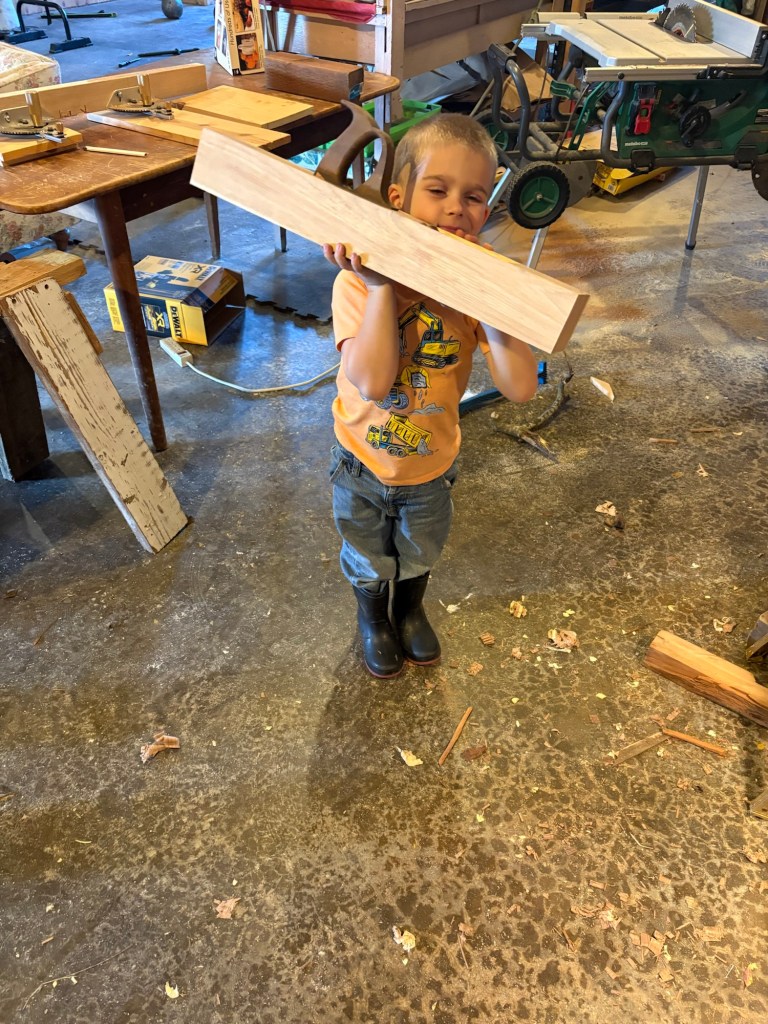
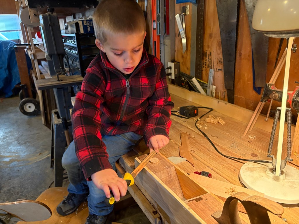
Seppi helped a good deal with this part.
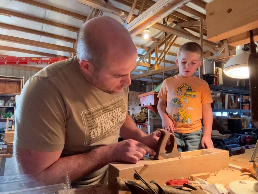
He was fascinated by the process of gently chipping out a little bit here, a little bit there, then fitting the handle.
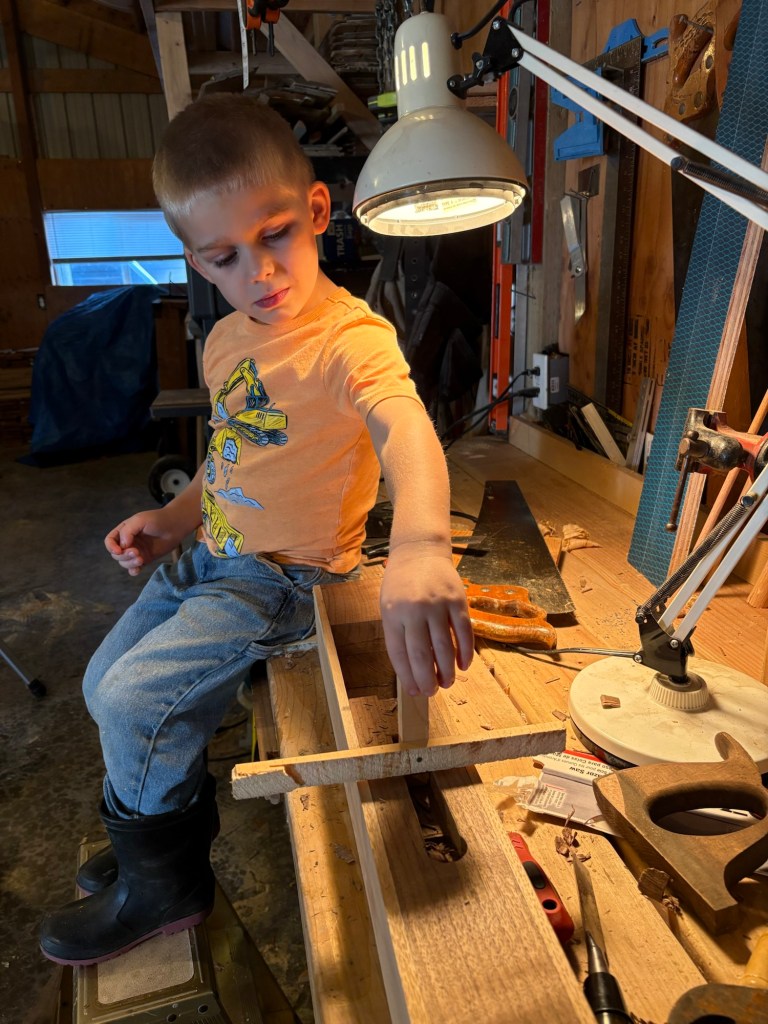
I went a little bit deep at one point so we made a little makeshift depth gauge he could use to check the depth as we went along.
Up to the line. Will it work?
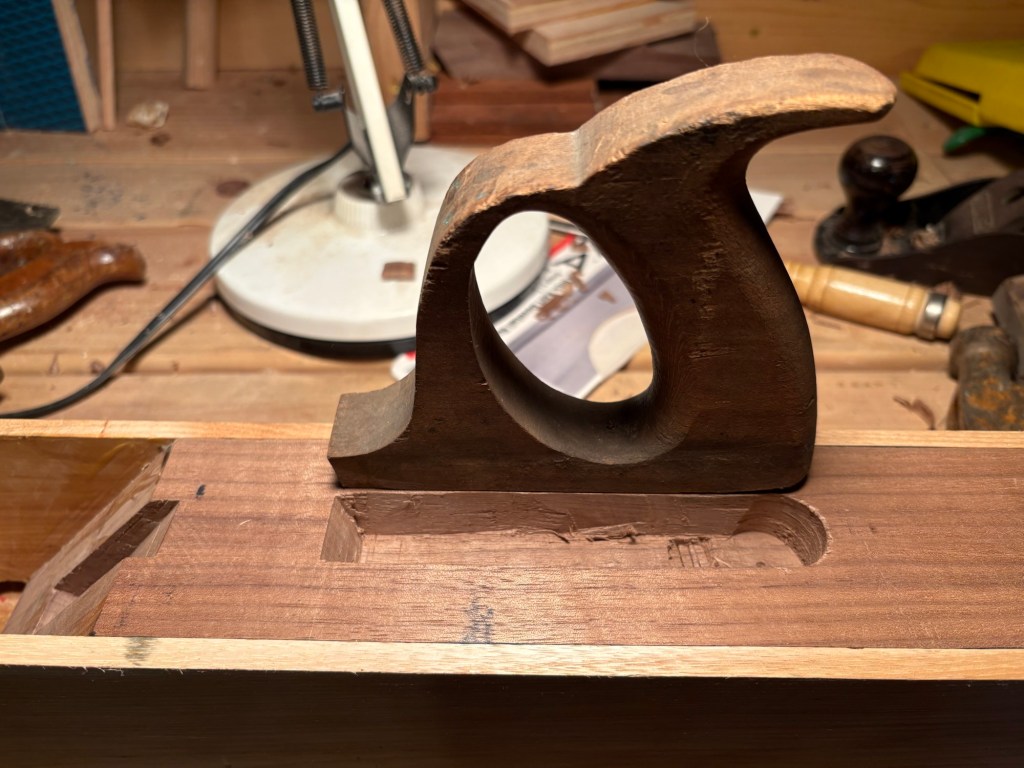
Looks close, but…
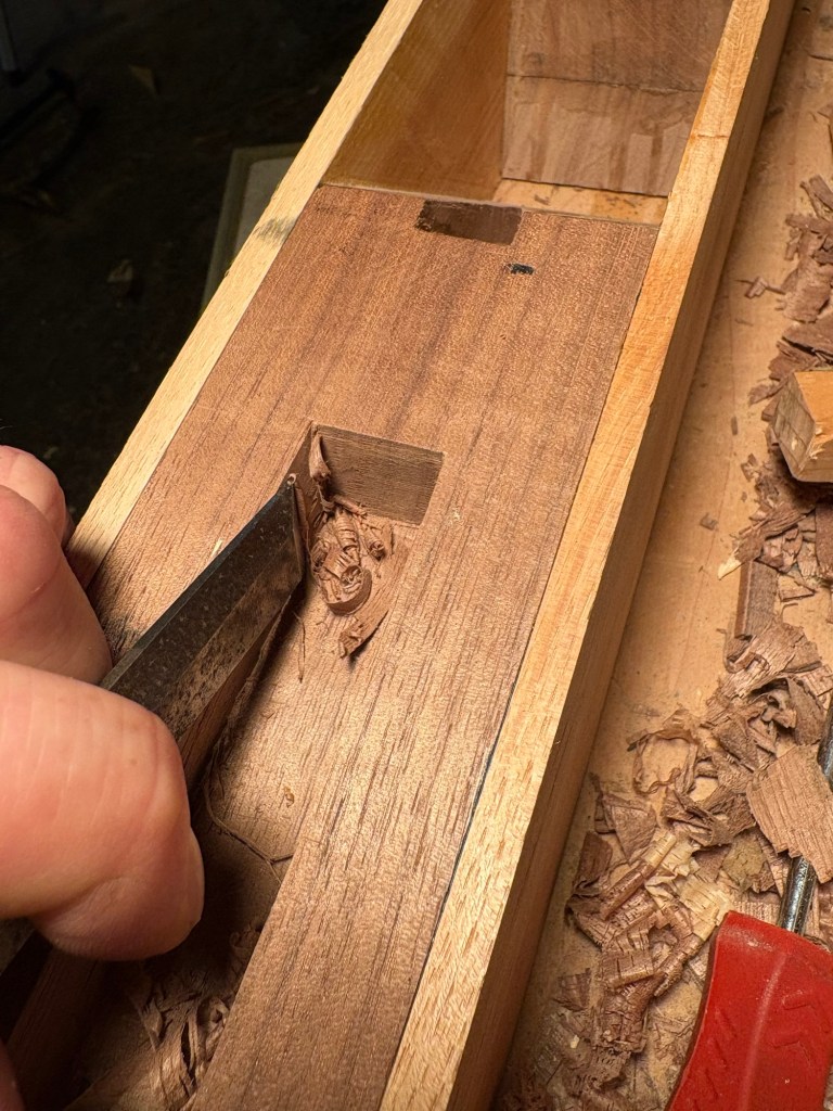
No dice. Too tight in the middle.
This is the slow part.
Painstakingly shaving off one curl here, another curl there.
Cleaning out the sides and corners.
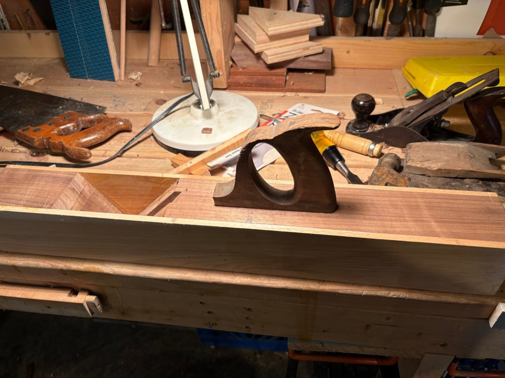
Until finally…
It’s all ready to go.
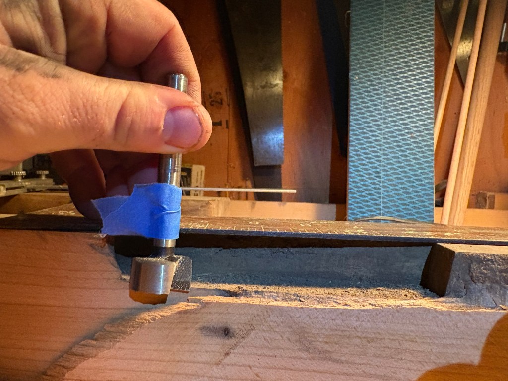
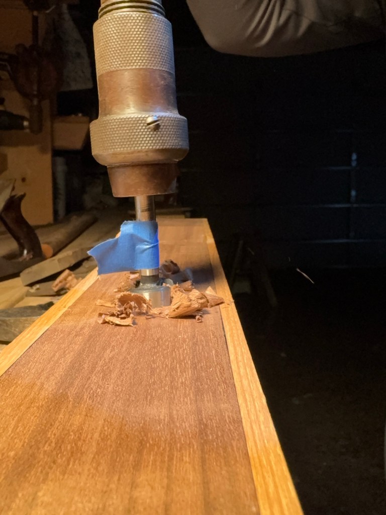
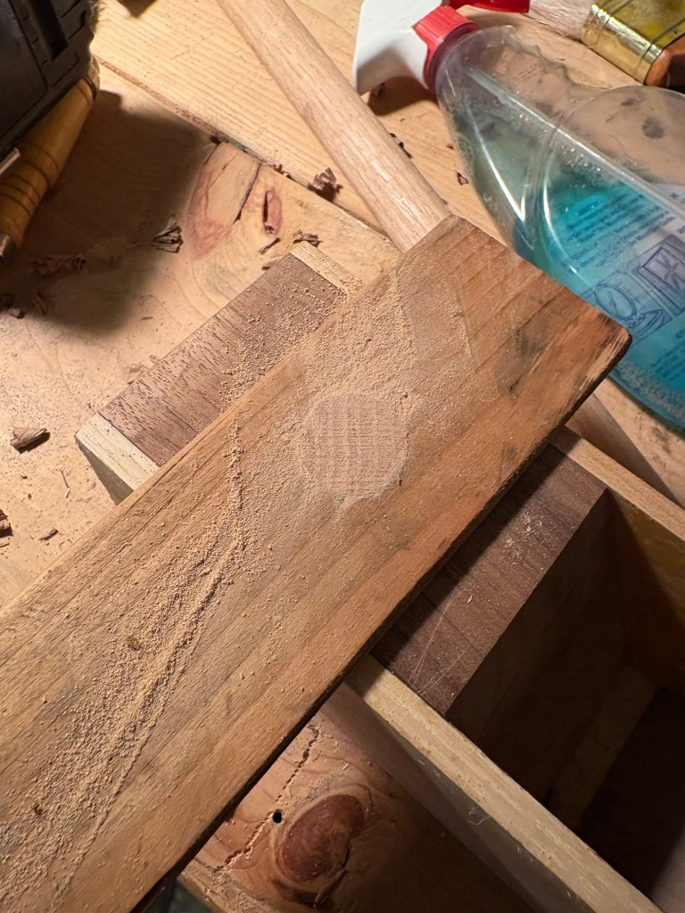
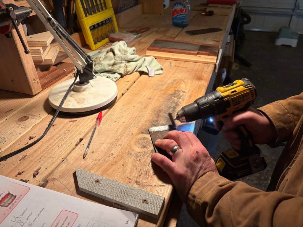
Then we need a strike plate. This is not strictly necessary, but it is good style and easy to add. In order to loosen the wedge after it is fully seated, we tap on the fore end of the plane with a hammer or mallet. A strike plate is a small, raised boss of hardwood to take the hammer taps so that you aren’t dinging up the actual body of the plane.
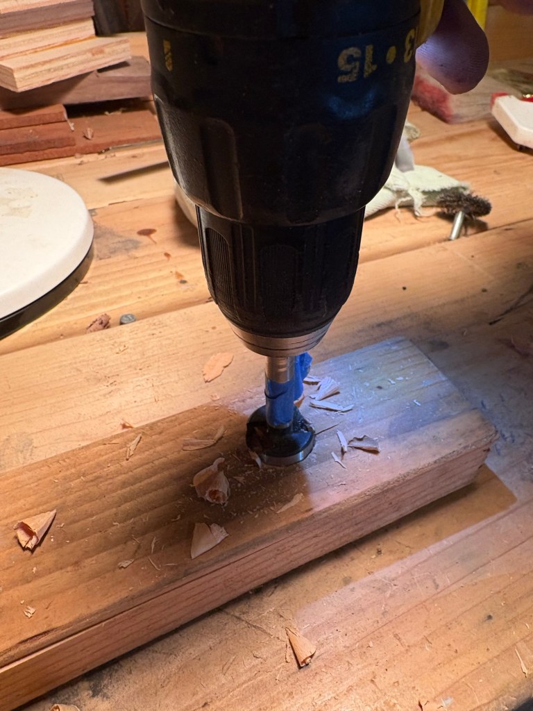
This is very easy to install. I drilled a 1″ hole about 1″ deep with a forstner bit. I marked the depth on a 1″ red oak dowel so that I would know when it was fully seated. Then I hammered it home.
To cut it off square I drilled through a shim of scrap 2×4 I cut on the table saw,
Slid that down the dowel,
And then cut it across with the pull saw.
This keeps the end of the boss square to the top of the plane.
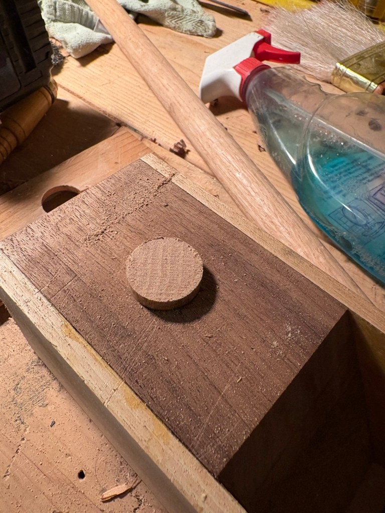
See?!
Because the strike plate is made out of oak, and oak is a “chippy” wood (meaning it likes to break off in little chips at exposed corners) we chamfered the edges of the strike plate.
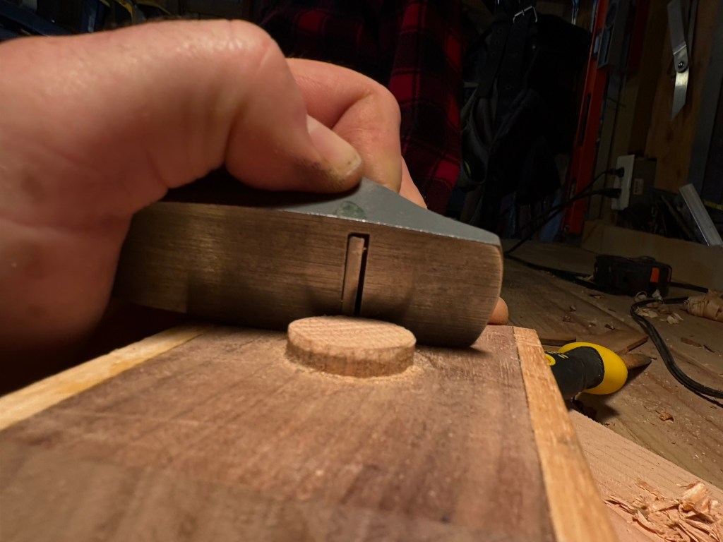
First with the Stanley 101.
Then with Seppi’s little file. That left some tooth marks, but oh well. It’s a working tool, not a display piece.
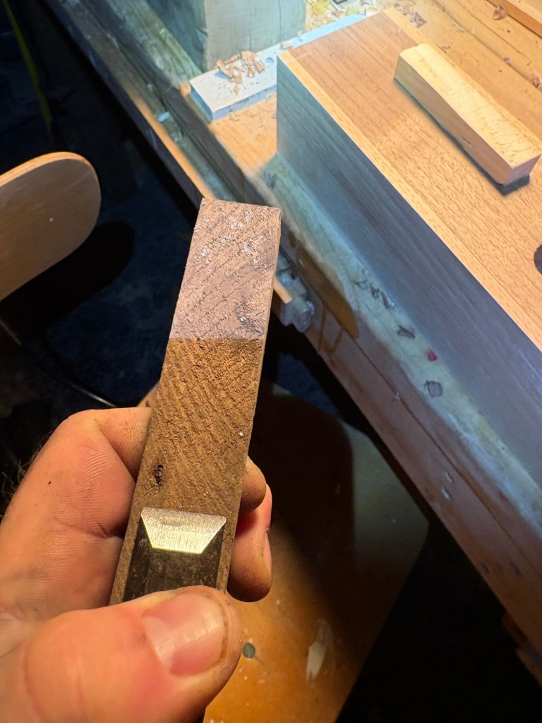
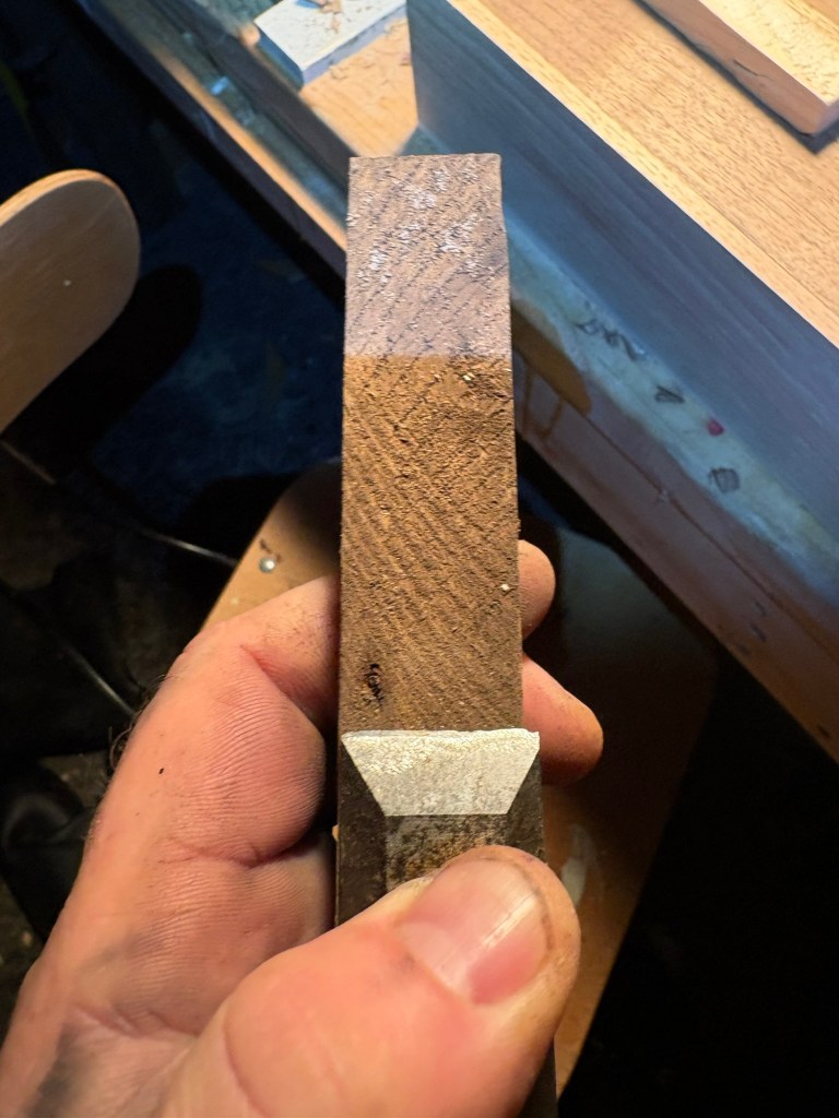
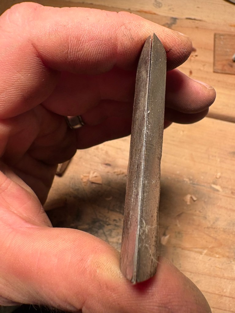
Now for the business end. The blade.
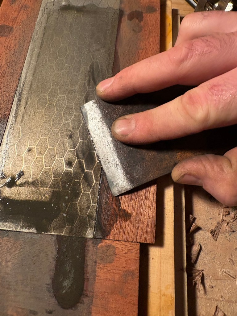
The blade was badly pitted, and the edge rounded. It took a full morning of going over it with the wire brush, then the diamond paper on a lapping board, and then on the 400 and 1000 grit diamond stones.
The chip breaker was in even worse condition. I cleaned it with the wire brush and tried to lap and sharpen the edge but not, as we shall see, well enough.
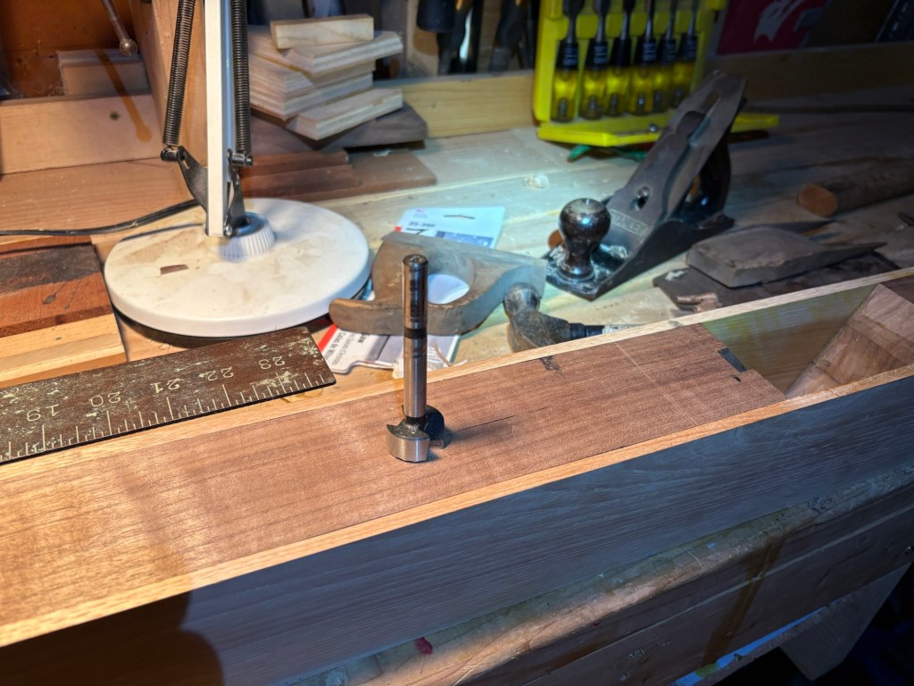
The final component is the dowel that will hold the wedge, and therefore the blade, in place.
Marking the spot on the inside, and then transferring the mark to the outside. This makes it easy to drill a 3/8 inch hole square with the drill jig.
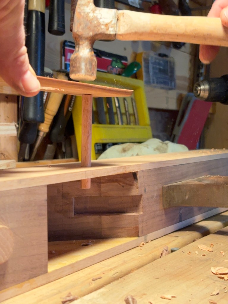
Then tap the dowel through the cheeks.
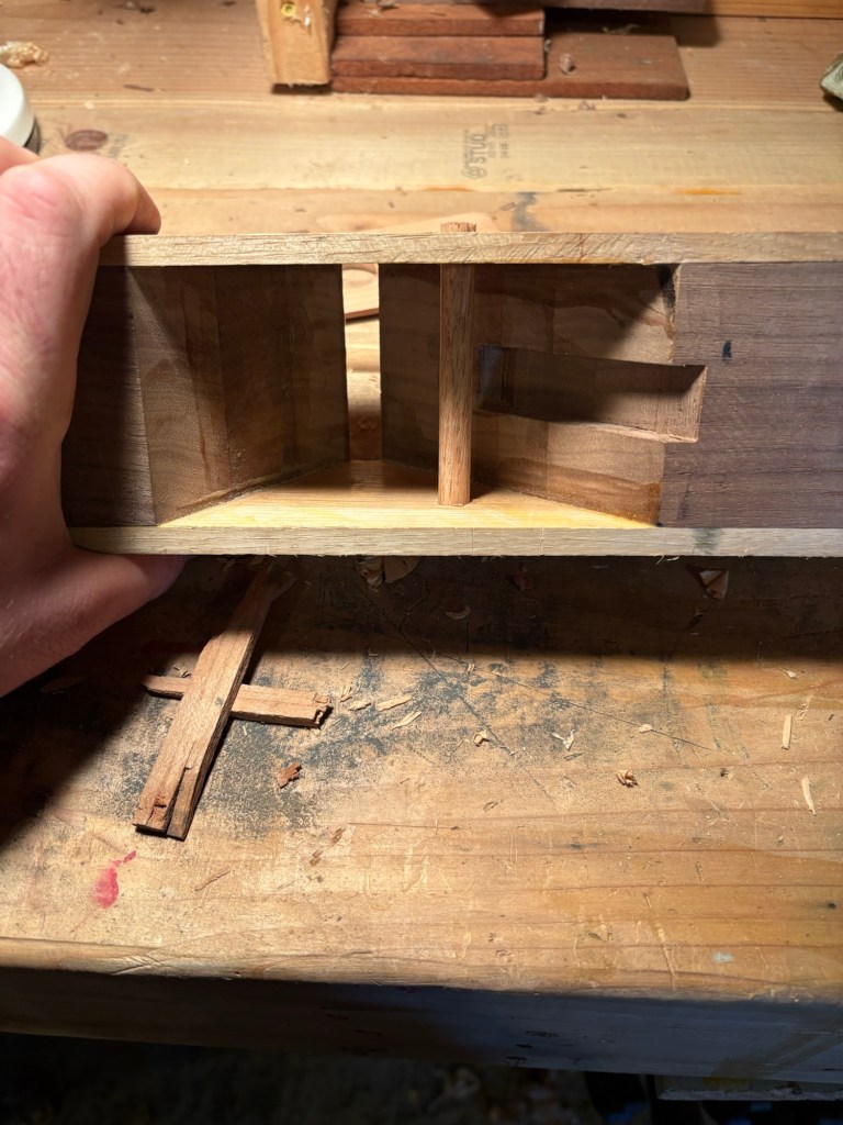
Until it sticks out on both sides. Then cut it flush with the pull saw.
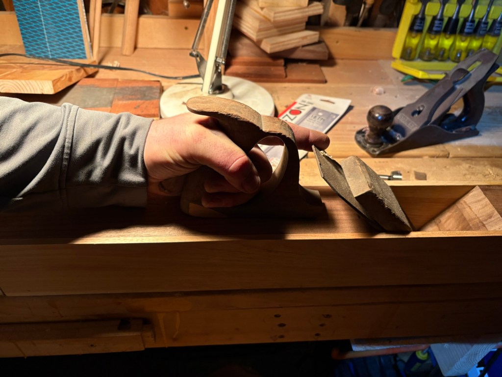
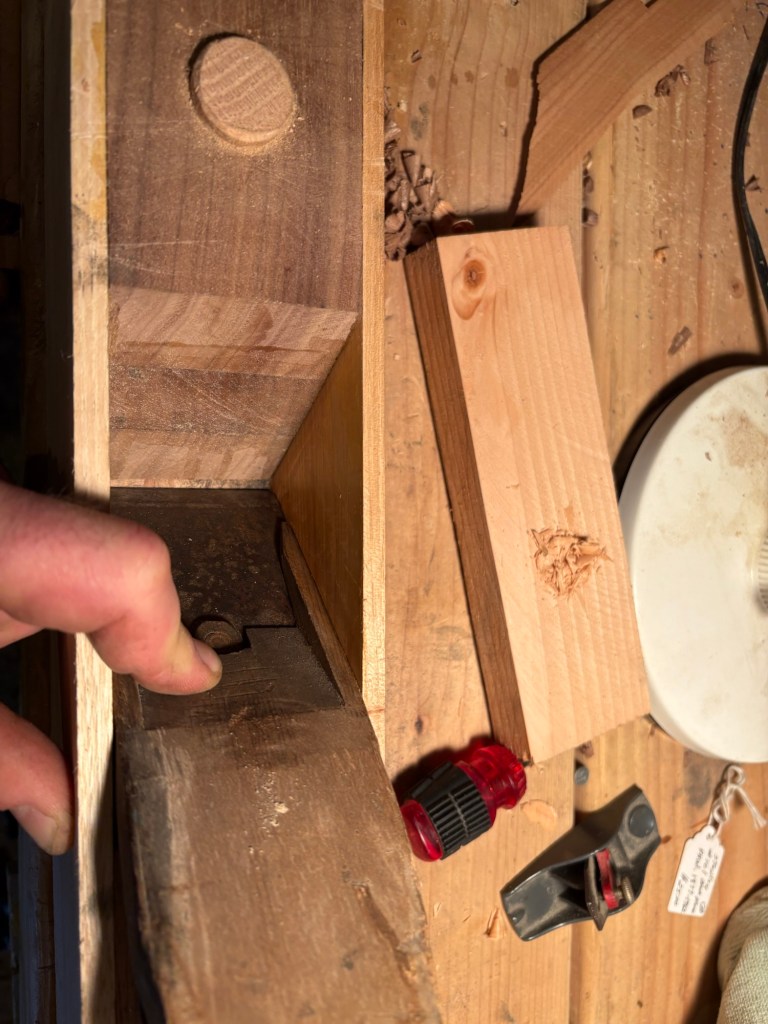
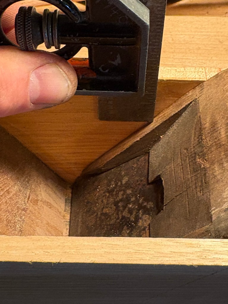
At this point I put the whole thing together and gave it a test run, but it did not plane very well. The blade kept gumming up with shavings. When I took it out and examined it, there was sawdust and shavings jammed in between the chip breaker and the blade. I should have taken a picture but I didn’t. The middle of the chip breaker was bowed or pitted so badly it was not making contact with the blade flush all the way across.
This resulted in almost an hour of careful sanding on the diamond paper, then the diamond stones, only to find that the edge was still bowed. So I had to put it on the grind wheel for a few turns (very carefully).
This was the final result, as good as I have gotten it so far. You can see it is still gapping on the top end. This is okay for the narrow stock I was testing it on, but will have to be fixed if I ever try to use it on something like a bench top where I need the full width of the blade.
Hey! It works!
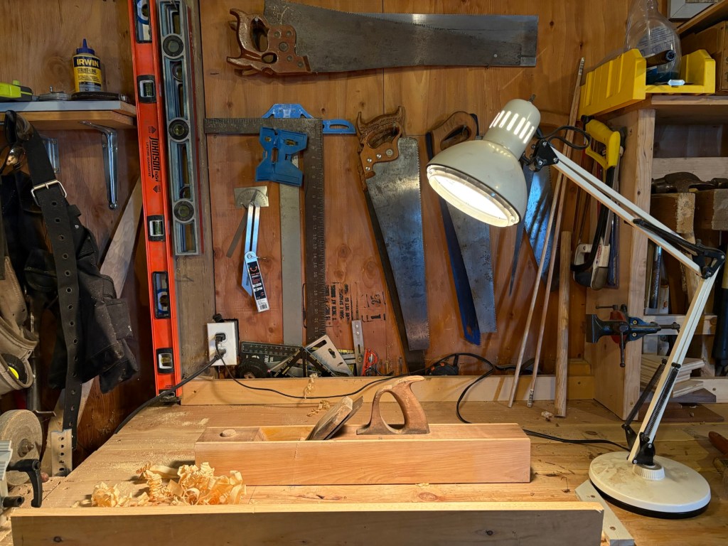
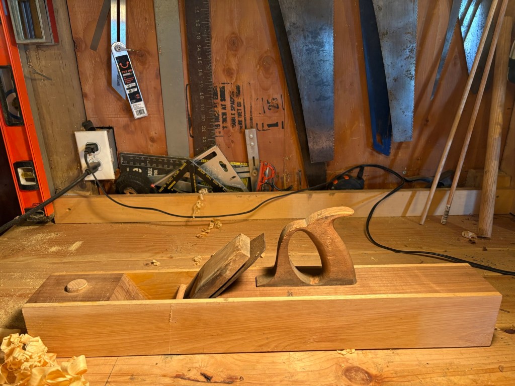
And there you have it. My first ever plane build.
